I built this distortion project, and I can't seem to get it to work. All I get is silence (i can hear some noise when I turn the 10K pot and when I insert a jack, but no guitar sound). I swapped the two diodes for IN4007's because that's all I could find. I also swapped the op amp from the TL071 to a 741 from Radio Shack. Could these swaps cause this problem?
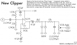
Here is the schematic I used.
Here is the schematic I used.
Attachments

Actually I believe the Diodes do make a differance...I believe The diodes limit the output voltage to 0.7v......
I have noticed this with pretty much every Distortion unit I have built that uses Clipping Diodes on the output....
If you use LED"s you will get much more output (1.5v) and a more Nu-metal sound....if you get rid of the diodes all together it will be a lot louder but the overdrive might not be very pleasant.....
Cheers
Thos resistors create a Voltage divider to give a Voltage referance at the input at half supply....You can use pretty much any 2 identical values accept too low a Value might cause your battery to drain quicker than usual....it should be fine with 15k....
Cheers
PS: you can also replace the 150k resistor in the feedback loop with a 100k-250k Potentiometer wired as a variable resistor which will let you dial in the ammount of gain you want, You can even put a switch on the Diodes so you can Enable/Disable diode clipping , or even put different diodes on a switch so you can get different Diode clipping tones , you can even use Mosfets as Diodes clippers but I like the sound of LED"s....
Minion said:Actually I believe the Diodes do make a differance...I believe The diodes limit the output voltage to 0.7v......
Which of course they do, and that's why they are there - but I was refering to using 1N4001 type rectifiers instead of 1N4148 type diodes - which I presume is what he was asking? (check the context of the previous posts).
Thanks so much for all the good info guys. I have one more question. If I was to lower the value of the 10K resistor that is between the diodes and the 100k pot, would I get more volume? I am not getting enough volume as compared to when the box is bypassed. Or would there be another route I could take to increase the gain?
Jman
Jman
Actually you would increse the 150k resistor to get more gain...
Actually the way the schematic is set up the gain is allready at 1000x (150r and 150k in feedback loop to set gain) which is plenty for an overdrive (Even overkill), but more Gain isn"t going to make it louder cuz Like I said before the Diodes on the output are going to limit the volume as they clamp the output voltage at 0.7v....Try takeing out the diodes and see how much louder it is , just too see that the curcuit is working correctly ,and if it is much louder then try LED"s because they will clamp the Output voltage at 1.5v which is double the output Voltage.....
Most Overdrive curcuits of this type have an aditional Clean Gain stage after the Diode"s to make up for the loss in Volume , you can do this your self by putting two of the same curcuits end to end minus the Diodes on the second stage.....
I actually use a curcuit that is allmost the same as this one(Minus the diodes and with less gain) as an active guitar pre-amp built into my Guitar , it works great and really helps overdrive the tubes in my amp and has a great tone.....
Cheers
I asked this on the chip amp forum, but I will ask again here as I didn't get an answer (I don't mean that rudely as the guys that helped me there were great!). Can I add another input for a ipod in parallel with the other input, or how would I go about that? Is it even possible? I have built a headphone amp for my bass guitar (basically the same type or curcuit without the diodes) and I wanted to add a jam-a-long input to it. The only difference is I have a simple buffer amp before the main amp to boost the guitar output. I would probably need to have the input after the buffer?
Here is the thread about the guitar amp. The final schematic I used was towards the end.
Thanks
Jeremy
Here is the thread about the guitar amp. The final schematic I used was towards the end.
Thanks
Jeremy
The issue with the circuit is that the input impedance is way too low for a guitar. The input impedance will be determined by the two 22k resistors in parallel, so it will be around 11k. A guitar amp should have at least 500k in input impedance in order to not load the pickups too much, so you should use two 1M resistors to be good.jman 31 said:Thanks so much for all the good info guys. I have one more question. If I was to lower the value of the 10K resistor that is between the diodes and the 100k pot, would I get more volume? I am not getting enough volume as compared to when the box is bypassed. Or would there be another route I could take to increase the gain?
Jman
Also Like I have said twice (no one seems to listen) is your output Voltage is Limited to 0.7v because of the Diodes which means that your Volume isn"t going to be very loud...Some Guitars put out more that 0.7v by them selves without a Booster so In theory the Curcuit could make your guitar quieter than without the curcuit....
runebivrin : Is right though, the input impedance is too low for proper signal transfer from your guitar through the curcuit...
Try adding a 1- 2m resistor from the input to ground...
If that doesn"t fix the Volume problem you are going to have to switch to LED"s (like I also said before) which will double your output Voltage, OR add another gain Stage.....
Cheers
Thanks Minion. I didn't mean to disregard what you are saying. I guess its just taking me a little bit to grasp it. I understand what you mean by the led's instead of the diodes, but I'm just getting a hang of the impedance issue. Please be patient with me. I really just enjoy this DIY stuff and definitely don't mean to be a pest.
I am going to study up, and try to understand how the input impedance works and then I will be back. I am willing to put in the effort to learn.
Jman
I am going to study up, and try to understand how the input impedance works and then I will be back. I am willing to put in the effort to learn.
Jman
No Problemm...Impedance is a very hard concept to grasp at first, but a Basic rule is the input impedance of a curcuit should be at least 5 to 10X the impedance of the signal it is amplifying for the signal to be transfered without loss.....
The ouput impedance of a Guitars pickup can be anywere from 5k to 100k so the input impedance of a guitar preamp should be at least 500k but 1M seems to be a standard value.....
Impeance and resistance are very simular accept Impedance changes with frequency.....
To set the input Impedance of a opamp curcuit you would generally put a resistor (of the Value you want to set the impedance to) from the signal input to ground .......
So if you want to set the Impedance to 1M you would put a 1M resistor from the input to ground......
Look at this schematic and see how there is a 2m2 resistor to ground at the input.....
http://www.generalguitargadgets.com/pdf/ggg_dist_250_sc.pdf
Also notice how it only uses the Virtual Ground for the Input Voltage referance and not anywere else, were your schematic uses the Virtual Ground for every ground...Most pedal curcuit I have built used the Virtual ground only on the input.....
Cheers
- Status
- This old topic is closed. If you want to reopen this topic, contact a moderator using the "Report Post" button.
- Home
- Live Sound
- Instruments and Amps
- Stomp Box Problems