After HOURS of searching and testing, I've found that the problem was insufficient sheilding. I had already sheilded the guitar cavities, but I also needed to shield the battery compartment and leads. Additionally, the piezo pickup input wires needed sheilding INSIDE THE ALREADY SHEILDED GUITAR CAVITY. I also twisted the signal and return wires.
The main lesson is, i guess, a single layer of copper tape (lining the main guitar cavity) is not enough shielding for the extreme sensitivity of the piezo buffer inputs.
The main lesson is, i guess, a single layer of copper tape (lining the main guitar cavity) is not enough shielding for the extreme sensitivity of the piezo buffer inputs.
Last edited:
It works!
The circuit works fine! I'm using this on an electric violin with the piezo mounted on the bridge (instead of wedging it between bridge foot and body).
The piezo have a resistance of abt 38Mohm & capacitance of 10nf~.
Now I have to work on balancing the tone of the output (and finish reading the thread)
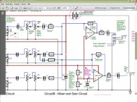
Hey there, seems the photo upload is working again. Here's the circuit schematic.
The circuit works fine! I'm using this on an electric violin with the piezo mounted on the bridge (instead of wedging it between bridge foot and body).
The piezo have a resistance of abt 38Mohm & capacitance of 10nf~.
Now I have to work on balancing the tone of the output
(and finish reading the thread)Stereo Modifications to the Circuit
I haven't posted for a couple of years now. Since the circuit I built last (with a lot of help from this forum, thanks again) has served me well and has been excellent in practise, I hadn't felt the need to change much. But now I'm starting to want even more control over the circuit, specifically stereo/multichannel output. I've run into an issue where I'm unsure as to how to "split" audio (i.e. to have it go to two separate outputs) whereby, if I only use one or both outputs the signal will remain unchanged (ie, in volume and timbre) and not affect the other output/circuit.
For example, in the new circuit I've posted here, does anyone know how it's possible to split the "mid" piezo so that it goes to both opAmps equally, while the low only goes to one opAmp, and the high only goes to the other opAmp.
I guess to start, could anyone tell me: will this require a simple or a complicated solution? Any info is greatly appreciated.
Attachments
Last edited:
Thanks for the quick reply mjf. Cool, so this could actually a pretty simple fix then, looking at your schematic. Thanks very much for this.
One thing I don't understand.. is it mainly the capacitors or the resistors (or both equally?) that block the "backwards" traveling of the audio signal?
One thing I don't understand.. is it mainly the capacitors or the resistors (or both equally?) that block the "backwards" traveling of the audio signal?
please take care, this is not a finished schematic......
there is no backwards travelling audio signal........the point after the 6,8k res is a virtual ground, that means the audio signal is (virtually) zero......no signal there (imagine: virtually connected to ground).
in reality there is a very small signal - in the dimension of the distortion signal.....0,00xxx volts , that is in real designs mostly ignored (simplyfied).
Last edited:
Thanks for the info mjf. I've modified the circuit how you suggested. I am guessing that I can't keep the old component values and have everything work like I want it, that would be too easy. So I'm trying to figure out how to set the right values. Is the easiest way to find these values by using a virtual circuit emulation program?
Attachments
Bipolar Power Supply
Hello there, in order to increase the "headroom" of the audio circuit, I'm interested in trying a Bipolar Power Supply/Dual Rails.
I've attached a schematic of my circuit with the proposed changes. Could anyone offer any insight into whether I've got this wired correctly or not? Or are there any other considerations when switching from a single to a dual rail system?
Attachments
Last edited:
I am not not sure exactly what I would propose as an alternative, but I personally am only familiar with the musical instrument jack TRS jack ring terminal being grounded by a TS plug as a power switch technique when it is used with a single battery.
My initial concern is that I see op amp(s) connected to the both voltage polarities regardless of the ground being opened/grounded by the jack as switch technique.
This appears to have 18 V total on the op amps with no ground. So it appears the op amps are sort of floating relative to ground and connecting/disconnecting the ground would/probably create a transient, in addition to the 'power off' function not really being effective.
2nd observation is that I see op amps still biased to 1/2 a single battery voltage. Going to bipolar power with the op amps still biased for single supply would likely put you op amp outputs at some other potential than they were before. Even if it stayed at 4.5V rather than moving to 13.5 or -4.5, it's still counterproductive to seeking more headroom on output swing.
I'm on a phone now & can't see while I type, but I didn't look at the JFET's bias to see if they are affected by the power supply change. I also didn't look for coupling (DC blocking) capacitors on the op amp outputs. That's normally needed with mid-bias single-supply operation of op amps. If the op amp bias DID change to a negative offset by virtue of the single-supply bias technique, electrolytic coupling caps could be unhappily reverse-biased.
As I said, I didn't study it carefully, so it may be that the mid-point bias remains at 4.5 V due to being directly connected to the +9 'bus'.
I think a DPDT switch for both batteries (+) with ground no longer jack-switched and disconnection of the op amp input power bias are things to analyze relevance of in your scenario.
thanks for the quick responses multi-volti and mjf
Oh sorry, I actually didn't mean to try and run this with a battery on switch jack, I just forgot to update the circuit diagram. I've updated it now (see new attachment)
I've circled the areas of concern you brought up multi-volti... do you know, would I change the resister values of R5/R6 to accommodate the dual rail system? Also, not sure about the capacitors C6 and C7, would I just omit them? or change their values?
Attachments
i think you can use two 9V batteries in series (instead of only one)......gives you 18V.
have a look if there are parts running hot.
so there's a possibility that I wouldn't need to change ANY components? (except add the additional 9V battery) In your opinion, would I simply add another 9V battery in series, as opposed to attaching to ground between the two batteries as I've indicated in the diagram?
'2134 op amp has max. power supply of +/- 18 VDC or 36 V total, so two 9V batteries is OK, for 18V total.
Do the JFET's work as drawn? The dual 22M set gate bias, but I see no drain or source resistors...the lower JFET looks like it's set up as a current source, but with the wide variation in JFET parameters, it doesn't look like a predictable biasing method.
I suggest you research 'noiseless biasing' for op amps and JFET boosters. The pair of 22M resistors looks like a recipe for a lot of thermal noise. Noiseless biasing typically does something similar to the op amp voltage divider...a pair of 10k to 100k resistors in series to bias the gate at half the Vdd voltage instead of the 22M resistors, then instead of the 1k feeding the gate, you use the high impedance you want, like 11M.
How is this working for you before making the current round of proposed changes?
I have not had the opportunity to listen to them; it's just that the LT1884 offers exceptionally low current draw while providing rail-to-rail voltage swing---these features would be of utmost importance in a battery-powered application, methinks.
LT1884/5 look like some nice op amps, but not a nice price...that's life with precision op amps...
- Status
- This old topic is closed. If you want to reopen this topic, contact a moderator using the "Report Post" button.
- Home
- Live Sound
- Instruments and Amps
- Piezo Film Buffer and Amp Combo for Guitar Electronics