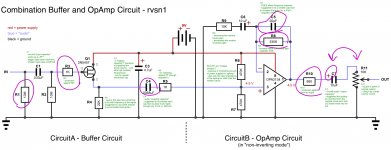
Hello there, thanks for all the responses and info. I've had some time to test out the audio of the circuit and swap components, etc. I've updated the circuit schematic to show my current components, values, etc. The following are a few revisions I've made and I list the reasons for each:
R1- I've made this 10M for simplicity (instead of 4.7M x2 = 9.4M)
R3- I've added this to protect against RFI, as mjf had suggested, and since the original "RF shunting" 1pF capacitor has been taken out
C4- Through testing, I've found that the original buffer circuit actually adds TOO MUCH low frequencies.... so I've used a 0.0068uF capacitor to gently roll off the lows at the right cutoff frequency
C5- I lowered this capacitor value to allow for more high frequencies through the opamp
R8- I increased this to increase the gain of the opamp
R10, C7, R11 (potentiometer) - I've rearranged and replaced these as suggested earlier in this forum discussion
_____
So with these revisions, I now find the overall frequency balance of the buffer circuit is very good, and the gain level of the opamp is also how I want it. But I'm not entirely happy with how the opamp circuit changes the overall frequency balance... it somehow adds low frequencies (and therefore the highs are not as clear as I would like). So my main question is: is there a way to make this opamp circuit more "transparent" (regarding not changing the frequency balance), and yet keep the same gain increase? So... I'm uncertain if the low frequencies are due to the current components in the circuit, or whether I have reached the limitations of the opamp. If it's due to the limitations of the opamp, I could try (as was suggested by Nigel before) to use more gain stages.
Any ideas....or hunches?
_____
since there is a problem with file upload at the moment, a pdf of the circuit can be found at the following link:
www.thenonanonymous.com/BAC-TemporaryWeblink/TemporaryWeblink.html
Hello there, thanks for all the responses and info. I've had some time to test out the audio of the circuit and swap components, etc. I've updated the circuit schematic to show my current components, values, etc. The following are a few revisions I've made and I list the reasons for each:
R1- I've made this 10M for simplicity (instead of 4.7M x2 = 9.4M)
R3- I've added this to protect against RFI, as mjf had suggested, and since the original "RF shunting" 1pF capacitor has been taken out
It won't do any harm, but it won't do any good either - mjf is mistaken in his assumption, it only applies to valve circuits.
C4- Through testing, I've found that the original buffer circuit actually adds TOO MUCH low frequencies.... so I've used a 0.0068uF capacitor to gently roll off the lows at the right cutoff frequency
C5- I lowered this capacitor value to allow for more high frequencies through the opamp
As there's currently no circuit, I don't where the capacitors are?, but there's NONE that will 'add low frequencies', unless they are in the feedback network. Likewise, there's none that will 'allow more high frequencies' either.
Lowering coupling capacitors will reduce low frequencies (that are present from the instrument, and supposed to be there), but it's a VERY poor way to try and provide tonal variations.
OK, got a circuit now 
R3 and R5 don't do anything, and are just a waste of two resistors.
C4 won't 'allow more highs', but will slope off low frequencies at 3dB per octave, above that frequency it will be flat.
C5 rolls off the high frequencies (by increasing feedback at higher frequencies), and by increasing R8 to give more gain, it will roll off lower down, so needs reducing as R8 increases.
But again, these aren't things you should be playing with for tonal variations, which will only be slight anyway, if you want frequency shaping then add it.
I think I might have found my main source of confusion- R1. I overlooked the influence this resistor can have on the frequency spectrum of the signal. This is where the excessive lows (into subsonic range) were coming from. I tried some listening tests with different resistors here and found that the lower the resistor value, the less low frequencies end up in the signal. The datasheet for the specific piezo films (the link to this can be found in my original post in this discussion) states "Min. impedance- 1MΩ, recommended 10MΩ". 10M for R1 is too high a value for my circuit. Does R1 determine the impedance into the piezo film... or, for example, is it a combination of R1 and C1 that determine this? Is there a calculated way to determine what value I should optimally use for R1, or should I simply find the right balance by trial and error listening tests? I have a hunch that it might be around 1M, or a little lower. On reflection, these sensors were originally designed to be vibration sensors, not specifically for audio use, so... subsonic frequencies might be desired in the case of, for example, sensing mechanical vibrations for use as a switch or something like that.
Anyways, I was trying to cut these subsonic frequencies created by R1 with the C4 capacitor there (effectively using it as a HPF). But I see that's the wrong way to do it, though i am surprised that it's even possible to do it.
Also, I've found through trial and error that C5 sounds best either with a 1pF capactor, or totally absent (I can't hear a difference). I tried a 20pF and THAT cuts the highs more than I like. Are there any negative consequences to removing C5 entirely?
Anyways, I was trying to cut these subsonic frequencies created by R1 with the C4 capacitor there (effectively using it as a HPF). But I see that's the wrong way to do it, though i am surprised that it's even possible to do it.
Point taken.But again, these aren't things you should be playing with for tonal variations, which will only be slight anyway, if you want frequency shaping then add it.
Also, I've found through trial and error that C5 sounds best either with a 1pF capactor, or totally absent (I can't hear a difference). I tried a 20pF and THAT cuts the highs more than I like. Are there any negative consequences to removing C5 entirely?
I think I might have found my main source of confusion- R1. I overlooked the influence this resistor can have on the frequency spectrum of the signal. This is where the excessive lows (into subsonic range) were coming from. I tried some listening tests with different resistors here and found that the lower the resistor value, the less low frequencies end up in the signal. The datasheet for the specific piezo films (the link to this can be found in my original post in this discussion) states "Min. impedance- 1MΩ, recommended 10MΩ". 10M for R1 is too high a value for my circuit. Does R1 determine the impedance into the piezo film... or, for example, is it a combination of R1 and C1 that determine this? Is there a calculated way to determine what value I should optimally use for R1, or should I simply find the right balance by trial and error listening tests? I have a hunch that it might be around 1M, or a little lower. On reflection, these sensors were originally designed to be vibration sensors, not specifically for audio use, so... subsonic frequencies might be desired in the case of, for example, sensing mechanical vibrations for use as a switch or something like that.
Again, it's not 'increasing the bass', it's passing it as it's supposed to be.
Lowering the value of the load resistor (just as with a passive guitar) excessively loads the pickup and thus kills the bass content. This 'may' be a desired effect, and there have been occasional guitar amps that have an 'input impedance' control on the front.
The input impedance is the two 10meg in parallel, so 5Meg.
Anyways, I was trying to cut these subsonic frequencies created by R1 with the C4 capacitor there (effectively using it as a HPF). But I see that's the wrong way to do it, though i am surprised that it's even possible to do it.
Point taken.
Also, I've found through trial and error that C5 sounds best either with a 1pF capacitor, or totally absent (I can't hear a difference). I tried a 20pF and THAT cuts the highs more than I like. Are there any negative consequences to removing C5 entirely?
No, it's only there to provide HF roll-off, and a 1pF capacitor is probably less than the capacitance of the construction - is it built on a PCB or what?.
No, it's only there to provide HF roll-off, and a 1pF capacitor is probably less than the capacitance of the construction - is it built on a PCB or what?.
Well it's currently on a breadboard, but I'll be soldering to one one of those open matrix PCBs
Well it's currently on a breadboard, but I'll be soldering to one one of those open matrix PCBs
Well there's no use messing about with small capacitors then, the capacitance of the breadboard will be greater than the capacitors you're fitting.
Personally I never use breadboards, far too restrictive on what you can do (although audio preamps 'should' be OK - although anything affected by small capacitance values may well perform differently).
The breadboard is definitely not ideal. I try and compensate for some of its flaws with a makeshift Faraday Cage (cardboard box lined with aluminum foil)... but it only sortof works. But I don't know of a different way that makes it so easy to test components, for practical listening A/B tests.
The breadboard is definitely not ideal. I try and compensate for some of its flaws with a makeshift Faraday Cage (cardboard box lined with aluminum foil)... but it only sortof works.
That seems a pretty pointless exercise
But I don't know of a different way that makes it so easy to test components, for practical listening A/B tests.
There's little need or reason to do so, simple design skills let you know what effect most components will have - and as I've said all along, if you're looking for tonal changes, add the circuits for doing it - don't try and bodge the basic circuit (which just stops it working properly).
Nigel, how easy is would it be to create a dedicated high pass filter to add to this circuit? I'm wondering if that's the way to go, rather than filtering out the low frequencies via lowering the input impedance.
You might enjoy a read of this:
http://www.ti.com/lit/ml/sloa088/sloa088.pdf
Thanks mjf and Nigel for the info and guidance.
I'm still getting some "coloration" of tone that I'm trying to track down... and so I've been searching for simpler solutions, and came across the beavisAudio.com website, good info for beginners there
Could you tell me if I replace the opAmp in the following circuit with the OPA2134, will it work, need additional revision, etc ?
If it won't add ANY gain, I'll stick with what I have... but... if this could combine the two circuits well it would simplify everything.
Attachments
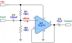
....this is a unity gain amp, voltage amplifikation=1, a "buffer" amp.......
I guess it's not as simple as adding a resistor to the feedback loop to increase gain? That would probably be too easy. Just in case this is not possible... I'll continue testing my current combo circuit... trying to learn more about why the processed sound is not as transparent as I would like it.
- Status
- This old topic is closed. If you want to reopen this topic, contact a moderator using the "Report Post" button.
- Home
- Live Sound
- Instruments and Amps
- Piezo Film Buffer and Amp Combo for Guitar Electronics