Hi all, my first post and I have a dilemma!
I'm all ready to start building a Gibson GA-8T clone but I wonder if I'm going down the wrong track.....
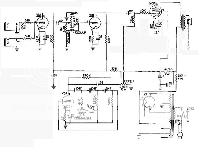
The GA-8T has a push pull 6BM8 output, 12AX7 preamp & uses the triode in one of the 6BM8s for tremolo.
The donor chassis I have is from a 6BM8 single ended circa 1950 radio which I was using "as is" for a guitar amp. The radio-amp sounded awesome through my 4x12" box, but was untested, probably unsafe and also I'd like to learn about shaping guitar tone. So the chassis was stripped and this build will be a running experiment.
The radio had a EZ80 rectifier while the Gibson has a 5Y3. I would need to punch a new hole to fit the 5Y3. Would the EZ80 be suitable for the Push Pull design? (it was powering 5 valves in the radio) and if so are there any changes required in the schematic?
Would the donor power transformer be suitable for a 5Y3?
My knowledge is fairly limited when it comes to current draw & supply (this is something I hope to come to grips with). How can I measure my power transformer's potential for output?
Also, I'm afraid that changing to P-P and a new OT will change the sound in a negative way. So my second option would be to re-build the amp as SE 6BM8 power section into the original OT, the tremolo circuit using the triode from the 6BM8 and a 12AX7 or two up front for experimenting.
I guess the third option is to build two amps")
Some advice or ideas would be greatly appreciated.
Ben.
I'm all ready to start building a Gibson GA-8T clone but I wonder if I'm going down the wrong track.....
The GA-8T has a push pull 6BM8 output, 12AX7 preamp & uses the triode in one of the 6BM8s for tremolo.
The donor chassis I have is from a 6BM8 single ended circa 1950 radio which I was using "as is" for a guitar amp. The radio-amp sounded awesome through my 4x12" box, but was untested, probably unsafe and also I'd like to learn about shaping guitar tone. So the chassis was stripped and this build will be a running experiment.
The radio had a EZ80 rectifier while the Gibson has a 5Y3. I would need to punch a new hole to fit the 5Y3. Would the EZ80 be suitable for the Push Pull design? (it was powering 5 valves in the radio) and if so are there any changes required in the schematic?
Would the donor power transformer be suitable for a 5Y3?
My knowledge is fairly limited when it comes to current draw & supply (this is something I hope to come to grips with). How can I measure my power transformer's potential for output?
Also, I'm afraid that changing to P-P and a new OT will change the sound in a negative way. So my second option would be to re-build the amp as SE 6BM8 power section into the original OT, the tremolo circuit using the triode from the 6BM8 and a 12AX7 or two up front for experimenting.
I guess the third option is to build two amps
Some advice or ideas would be greatly appreciated.
Ben.
Attachments
The donor power transformer is unlikely to be suitable for a 5Y3 restifier as it requires a 5V heater winding whereas the EZ80 is a 6.3V heater.
I would also doubt that it has sufficient high voltage winding current capability to run push pull 6BM8s although the EZ80 would cope OK. Rebuild this one as a Single End 6BM8 using the donor output transformer.
There is no easy way to really measure a power transformers power capability although a knowledgable tech can make estimates. Basically the power tranny will have a VA rating. VA meaning volts times amps. You take the existing "donor" design and work out the VA for each secondary winding then add them all together for the transformers VA rating. You can then mess around a bit, for example drawing a liitle more from the High Voltage secondary as long as you then draw a little less from the heater winding. The trick is to not exceed the total VA rating. Since the donor was a radio it is almost certain that the power tranny in it was rated just high enogh to do the job with no real excess capacity. Thats why I'm suggesting that it won't cope with a push pull 6BM8 output stage.
VA rating is used rather than watts (Hang on do I here you say - watts is just volts times amps right?, actually VA and watts are only the same if the voltage and current waveforms have the same phase, otherwise they are different and the watts can be less than the VA, so transformer ratings are in VA not watts.)
If you want to do a Push Pull 6BM8 later then start that one from scratch.
Hope this helps.
Cheers,
Ian
Last edited:
So I've decided to go with Ian's and build a (fairly) quick SE design with virtually the same circuit as the schem in my first post, only with a single ended output.
Correct me if I'm wrong, but, this should be achievable because one of the 6BM8s is using the triode section as a phase inverter. The pentode section becomes half of the PP output.
Is there anything stopping me (besides my lack of experience) from adapting a SE output to this design? I'm guessing there needs to be some sort of coupling cap?
I've been reading a PDF that I found somewhere called "Designing Valve Preamps for Guitar and Bass : Chapter 1- The Common Cathode, Triode Gain Stage"
I would like this build to be my working prototype for designing my perfect gain stages, eventually using 2 preamp valves.
You do not need the phase inverter stage, it operates at about a gain of one anyway so a SE output tube could run right after the first two stages. You will have to use an appropriate value cathode resistor on the output, probably the one you have now. I would guess the output and tremolo on the output will work if you just remove the bottom half of the circuit.
I have drawn up the schem for what I want to achieve, besides some R & C values, is this topology correct?
I don't know where the DEPTH pot should connect the tremolo stage to the output. After C5?
Is R9 required? It was part of the inverter in the old circuit I think.
Have I put the GAIN control in the right spot?
So far I'm assuming that my B+ will be correct. Next task is to measure my PT.
I would really appreciate any help with this one as I learn. I have a friend who is comfortable with very high voltage but doesn't know anything about tubes. He's going to help me out with a variac when it comes time to turn this on.
Attachments
Can't see any detail on your schematic. I was thinking of something like this. Mind you there are SE amps out there with tremolo, it might be good to check what I think might work.
An externally hosted image should be here but it was not working when we last tested it.
- Status
- This old topic is closed. If you want to reopen this topic, contact a moderator using the "Report Post" button.
- Home
- Live Sound
- Instruments and Amps
- 6BM8 guitar amp - SE or PP?