Alright, here is the state of the project:
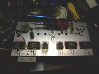
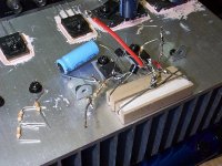
I'm going to rewire the entire circuit on my shiny new amp testbed (see picture). I absolutely abhor using copper wire, since the solder doesn't stick to it and it tarnishes so darn fast. So I'll probably end up cannibalizing that silver stuff they use from some device sitting around. I'm running out of solder or I'd probably have it built already. I haven't been able to find those Ge transistors and try them out on the Allison, but the Allison will remain constructed while I work on the headamp so I can wire it up whenever I find them. After the headphone amp is set up I will even be able to use it as a frontend for the Allison and drive speakers.
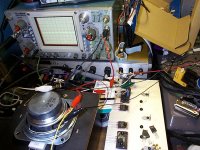
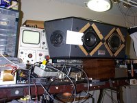
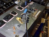
In the meantime, here is the Allison running. It produces sound. Surprise surprise, it sounds a lot like the speaker I connect it to (so it doesn't sound that great...)! I'm too afraid to test it on my new speakers, banish the thought. However a family member came by and commented on the "really smooth" sound, for what it's worth (this person is very sensitive to high pitched noises, so perhaps she would know?).
I planned for it to run at +-15V, but +-6V is already more than enough for my speakers, and at this point the drivers and outputs begin to get hot.
- keantoken
I'm going to rewire the entire circuit on my shiny new amp testbed (see picture). I absolutely abhor using copper wire, since the solder doesn't stick to it and it tarnishes so darn fast. So I'll probably end up cannibalizing that silver stuff they use from some device sitting around. I'm running out of solder or I'd probably have it built already. I haven't been able to find those Ge transistors and try them out on the Allison, but the Allison will remain constructed while I work on the headamp so I can wire it up whenever I find them. After the headphone amp is set up I will even be able to use it as a frontend for the Allison and drive speakers.
In the meantime, here is the Allison running. It produces sound. Surprise surprise, it sounds a lot like the speaker I connect it to (so it doesn't sound that great...)! I'm too afraid to test it on my new speakers, banish the thought. However a family member came by and commented on the "really smooth" sound, for what it's worth (this person is very sensitive to high pitched noises, so perhaps she would know?).
I planned for it to run at +-15V, but +-6V is already more than enough for my speakers, and at this point the drivers and outputs begin to get hot.
- keantoken
Attachments
I haven't tried them, didn't think of it. However it would allow me to use one of those dual .22 ohm resistors you get by the handful from dead amplifiers... I'll wire it up next.
PS: Aren't MOSFET's nearly indestructible?
- keantoken
Thought I gave you a handful of brand new 0.22??? Used is fine...
MOSFETs indestructible? Hardly. I blew up FOUR in one misevent
at TI's high voltage lab! I don't work there, I was just visiting to
test something at 390V that we build for them under contract.
Mine was not even the loudest MOSFET *BANG* heard that day.
All were generic MOSFETs that blew out, nothing made by TI.
But anyways, the gate is the most sensitive, you need a fast
Zenier of no more than 10-12V. And if you drive an inductive
load, you need a freewheel diode in parallel. Sometimes the
parasitic body diode is good enough, sometimes you need to
add one...
The .22 ohm resistors were the perfect width to go from emitter to emitter of the output devices... EXACTLY.
EDIT: Okay, I realize this response doesn't make any sense. What I meant to say was:
I used two dual .22 ohm resistors, one per output which gives .44 ohms per output, giving 1.3A bias for the Allison. This would take 8 of those .12 ohm resistors you gave me. Even with germaniums, it would take 4. More economical to use the old ones...
- keantoken
Last edited:
Leave em connected as-is, and just short across one .22 per output emitter.
Though thats only 1.13A if Germanium comparator drops are 0.25V apiece.
Why your class A quiescent only 1.3A anyways? When you got 6A supplies?
If your trying for AB, you need some diode curve. Can't get there with just
resistors across the gap. I don't think AB was your intent, so I can't fathom
why so much resistance was used?
Then again, you got 25ohm series resistance added to your speaker, I don't
think you could tell any difference 50 ohms between emitters.
Last edited:
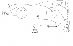
My supplies can push more than a few amps, but grounding is just an alligator clip between the ground terminals on the caps and I fear hum may be too much if I increase the supply. I also don't know how much my variac or the several in-line fuses will take.
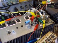
Actually with +-6V the amp doesn't have enough voltage swing for a 25 ohm resistor. A 4 ohm has been good enough for testing purposes. I'm testing this with my old kevlars and a few salvaged speakers.
I've attached an image of how I have my grounding set up... I suppose I could slide the alligator position along the wire between the caps, I'll have to test that but I think I tried it and found tests negative...
- keantoken
Attachments
Smoking-amp give you drafting lessons? Or you finally got old enough to drink?
Drop the crayon and back away slowly...
Drop the crayon and back away slowly...
Gee, is it really that bad? Maybe if I turn my head just right... 
Too much Dr. Pepper I guess... *burp*
*hic*
- keantoken
Too much Dr. Pepper I guess... *burp*
*hic*
- keantoken
Alright, a further state of the project:
I think the circuit itself is becoming finalized. I may add some things for improved clipping.
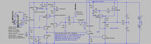
I am going to test out a current-type compensation, C5. I've trivialized the "niceness" function. If the Niceness is turned up, even harmonics are boosted but of very low order. The amount of odd harmonics will vary but will always be very low, and I believe this can be tweaked with the Balance resistors. C8 and C7 serve to filter ripple and increase PSRR, as well as facilitate the "niceness". I may opt, instead of putting the offset resistor between the bases of the Rush pair, to turn R5 into a trimmer, which is more trivial from a design standpoint. However I've never seen this done.
There is a mathematical relationship between all these values and the harmonic profile, I will see if I can determine it and make a flowchart for customizing the NTP this way...
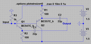
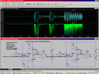
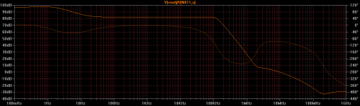
Attached is the FFT of a sine input with "niceness" turned all the way up. This is measured at about 1mW into 60 ohms; to get 4ths above 3rds here would be a feat of matching since levels are so low. I've also attached a circuit you can build and test out. Hook up a preamp or something and listen to your voice shifted up an octave! Scope shot of the same circuit, doubling a 500Hz tone. And then, a music file played through on the simulator...
It should be noted that 2nd harmonic generation depends on input more than it does the circuit itself. It depends on the music signal, and a sine wave tone cannot reveal this. Matching devices won't matter unless you're one listening to sine waves. As long as the music is above a certain volume, you will be getting virtually the same amount of 2nd harmonics.
- keantoken
I think the circuit itself is becoming finalized. I may add some things for improved clipping.
I am going to test out a current-type compensation, C5. I've trivialized the "niceness" function. If the Niceness is turned up, even harmonics are boosted but of very low order. The amount of odd harmonics will vary but will always be very low, and I believe this can be tweaked with the Balance resistors. C8 and C7 serve to filter ripple and increase PSRR, as well as facilitate the "niceness". I may opt, instead of putting the offset resistor between the bases of the Rush pair, to turn R5 into a trimmer, which is more trivial from a design standpoint. However I've never seen this done.
There is a mathematical relationship between all these values and the harmonic profile, I will see if I can determine it and make a flowchart for customizing the NTP this way...
Attached is the FFT of a sine input with "niceness" turned all the way up. This is measured at about 1mW into 60 ohms; to get 4ths above 3rds here would be a feat of matching since levels are so low. I've also attached a circuit you can build and test out. Hook up a preamp or something and listen to your voice shifted up an octave! Scope shot of the same circuit, doubling a 500Hz tone. And then, a music file played through on the simulator...
It should be noted that 2nd harmonic generation depends on input more than it does the circuit itself. It depends on the music signal, and a sine wave tone cannot reveal this. Matching devices won't matter unless you're one listening to sine waves. As long as the music is above a certain volume, you will be getting virtually the same amount of 2nd harmonics.
- keantoken
Attachments


Okay, I've got it working.
Very interesting!!! Definitely distortion!!! I have to take back my remark about listening to your voice and octave higher... It would be, but very harsh and hardly recognizeable.
It doesn't produce non-musical tones, I can tell that much. It does move the mid up to treble so everything sounds like a snare...
Might make a good distortion pedal...?
- keantoken
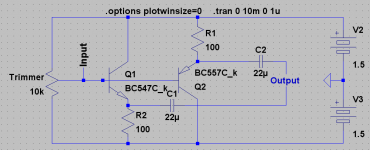
Here is an improved circuit which allows you to totally "tune out" the fundamental. It is easy to do when listening to sine waves...
I have no doubts this circuit could be used in RF to double the broadcast frequency.
Well, listening to bass, I think it could make a pretty good X-bass circuit...
- keantoken
I have no doubts this circuit could be used in RF to double the broadcast frequency.
Well, listening to bass, I think it could make a pretty good X-bass circuit...
- keantoken
Attachments
Last edited:
I never got to listen to the audio file I ran through in LTSpice because it would crash before the file got done... Judging by what I just heard it wouldn't be much though.
I haven't gotten to build the actual amp yet.
- keantoken
I haven't gotten to build the actual amp yet.
- keantoken
Oh wow!
I recently got this bag full of 22nF caps, and I've been using them to make this.
On one side, they say 223, on the other, they say 604! So they could either be 22nF, or 600nF. I'm betting on 22n, since it's a more standard value...
The first side reads 223, with C1K under it, the second side reads 604, with RAT under it...
- keantoken
Oscillation at 500KHz!
It is working. Before I change the compensation I will add some decoupling caps.
- keantoken
It is working. Before I change the compensation I will add some decoupling caps.
- keantoken
Next thing I try will be a 10R resistor in series with C5... Giving this cap 0.1R series resistance in the simulator gives remarkably similar oscillation as what I observed on my scope.
The series resistor is not a well-known technique when it comes to stability compensation. Kenpeter taught me this trick. We shall see...
- keantoken
The series resistor is not a well-known technique when it comes to stability compensation. Kenpeter taught me this trick. We shall see...
- keantoken
- Status
- Not open for further replies.
- Home
- Amplifiers
- Headphone Systems
- Rush Cascode Headphone Amp + JLH Output Stage