Hi M.
I am not exactly sure how to answer your question, but here is what I found in te PGA2311 datasheet.
SWITCHING CHARACTERISTICS
Serial Clock (SCLK) Frequency fSCLK 0 6.25 0 6.25 MHz
Serial Clock (SCLK) Pulse Width LOW tPH 80 80 ns
Serial Clock (SCLK) Pulse Width HIGH tPL 80 80 ns
MUTE Pulse Width LOW tMI 2.0 2.0 ms
Input Timing
SDI Setup Time tSDS 20 20 ns
SDI Hold Time tSDH 20 20 ns
CS Falling to SCLK Rising tCSCR 90 90 ns
SCLK Falling to CS Rising tCFCS 35 35 ns
Output Timing
CS LOW to SDO Active tCSO 35 35 ns
SCLK Falling to SDO Data Valid tCFDO 60 60 ns
CS HIGH to SDO High Impedance tCSZ 100 100 ns
That is from the table in the datasheet. on page 3")
On page 8 there is more information on the serial port.
Thanks for looking.
I am not exactly sure how to answer your question, but here is what I found in te PGA2311 datasheet.
SWITCHING CHARACTERISTICS
Serial Clock (SCLK) Frequency fSCLK 0 6.25 0 6.25 MHz
Serial Clock (SCLK) Pulse Width LOW tPH 80 80 ns
Serial Clock (SCLK) Pulse Width HIGH tPL 80 80 ns
MUTE Pulse Width LOW tMI 2.0 2.0 ms
Input Timing
SDI Setup Time tSDS 20 20 ns
SDI Hold Time tSDH 20 20 ns
CS Falling to SCLK Rising tCSCR 90 90 ns
SCLK Falling to CS Rising tCFCS 35 35 ns
Output Timing
CS LOW to SDO Active tCSO 35 35 ns
SCLK Falling to SDO Data Valid tCFDO 60 60 ns
CS HIGH to SDO High Impedance tCSZ 100 100 ns
That is from the table in the datasheet. on page 3
On page 8 there is more information on the serial port.
Thanks for looking.
Hi Russ...
I was looking for this.
lemme see what i can do...
wish me luck...
~M.
I was looking for this.
Russ White said:
Serial Clock (SCLK) Frequency fSCLK 0 6.25 0 6.25 MHz
lemme see what i can do...
wish me luck...
~M.

Internal or not to internal
Hi Russ,
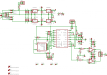
Just a small question. I was looking at your schematic, and realised you have not included a crystal.
If you are, what speed would you like it to run at? I assume 8MHz.
Please let me know.
Also, one small question. Instead of having a rotary encoder and stuff; have you given thought about a Digital Pot and IR(or RF ) remote?
thats all for now.
~M.
Hi Russ,
Just a small question. I was looking at your schematic, and realised you have not included a crystal.
If you are, what speed would you like it to run at? I assume 8MHz.
Please let me know.
Also, one small question. Instead of having a rotary encoder and stuff; have you given thought about a Digital Pot and IR(or RF
) remote?thats all for now.
~M.
Re: Internal or not to internal
Nope no chrystal intended. It should not be necessary I don't think.
The only human interface is from a 5K pot with the wiper read by the ADC to get my value for the PGA2311.
I have given though about the IR or RF, but I wanted to get this simple example working first.
In fact if I couldjust get the part to send the serial data to the PGA2311 I would be happy.
Thanks!
Hmmmm...saltnpeppah said:Hi Russ,
Just a small question. I was looking at your schematic, and realised you have not included a crystal.
If you are, what speed would you like it to run at? I assume 8MHz.
Please let me know.
Also, one small question. Instead of having a rotary encoder and stuff; have you given thought about a Digital Pot and IR(or RF
thats all for now.
~M.
Nope no chrystal intended. It should not be necessary I don't think.
The only human interface is from a 5K pot with the wiper read by the ADC to get my value for the PGA2311.
I have given though about the IR or RF, but I wanted to get this simple example working first.
In fact if I couldjust get the part to send the serial data to the PGA2311 I would be happy.
Thanks!
Re: Internal or not to internal
12F683 has an internal oscillator -- you also use the power supply for VREF.
These are wonderful devices to work with.
Russ -- as you know what you want to accomplish in VB perhaps using a BX24 from Netmedia would ease your implementation --
saltnpeppah said:Hi Russ,
Just a small question. I was looking at your schematic, and realised you have not included a crystal.
12F683 has an internal oscillator -- you also use the power supply for VREF.
These are wonderful devices to work with.
Russ -- as you know what you want to accomplish in VB perhaps using a BX24 from Netmedia would ease your implementation --
Here is what I have so far, it compiles, butr I have not tested it yet.
Code:
#include <pic.h>

#define Clk GPIO4
#define Data GPIO2
#define CS GPIO1
#define POT GPIO0;

writeByte(int out) {
	int b = out;
	int i;
	for (i = 8; i > 0; i--) {
		int x = 1 << (i-1);
		if (b >= x) {
			Data = 1;
			b -= x;
		}
		else
		{
			Data = 0;
		}
		Clk = 1;
		Clk = 0;
	}
}

writeState(int val){
	CS = 0;
	writeByte(val);
	writeByte(val);
	CS = 1;
}

int getState() {
	GODONE = 1;
	while (GODONE){
		NOP();
	}
	return ADRESH;

}

main() {
	ANSEL = 1;
	ADCON0=0b001110001;
	TRIS1 = 0; // make output
	TRIS2 = 0; // make output
	TRIS4 = 0; // make output
	CS = 1;
	while (1) {
		writeState(getState());
	}
}More complete....
Code:
#include <pic.h>

#define POT GPIO0;
#define CS GPIO1
#define Data GPIO2
#define ZCEN GPIO3;
#define MUTE GPIO4;
#define Clk GPIO5

writeByte(int out) {
	int b = out;
	int i;
	for (i = 8; i > 0; i--) {
		int x = 1 << (i-1);
		if (b >= x) {
			Data = 1;
			b -= x;
		}
		else
		{
			Data = 0;
		}
		Clk = 1;
		Clk = 0;
	}
}

writeState(int val){
	CS = 0;
	writeByte(val);
	writeByte(val);
	CS = 1;
}

int getState() {
	GODONE = 1;
	while (GODONE){
		NOP();
	}
	return ADRESH;

}

main() {
	int i = 0;
	ANSEL = 0b001110001;
	ADCON0 =0b000000001;
	TRIS1 = 0; // make output
	TRIS2 = 0; // make output
	TRIS3 = 0; // make output
	TRIS4 = 0; // make output
	TRIS5 = 0; // make output
	MUTE = 1;
	ZCEN = 1;
	CS = 1;
	while (1) {
		writeState(getState());
		for (i = 0; i <2000; i++) NOP();// delay
	}
}hmm, Russ,
No register setup (WDT,OSCmode,fuse set, etc...) ?
No start up MUTE delay timing (<20mS) ?
And, not use a continuos read-write loop.
In my soft, the write routine it is execute only if dac value != of previus data, for threshold to the minimum the PGA writing (Digital noise).
In the normal conditions, the PGA do not write...
The internal osc clock has to be to very low frequency, to reduce the troubles.
With my PIC12F675 I have used 4MHZ (only value), but if the PIC12F683 have a lower osc, use it...
PS: normally are used "byte" definitions ( 8bit data ), to the place "int" (16bit data) ,obviously with ansi C compatible... (because the PIC elaborates only 1 bytes to the time)
Ciao
Mauro
getting closer....
Code:
#include <pic.h>


__CONFIG(INTIO & WDTDIS & PWRTEN & MCLRDIS & UNPROTECT & BORDIS);

#define POT GPIO0
#define CS GPIO1
#define Data GPIO2
#define ZCEN GPIO3
#define MUTE GPIO4
#define Clk GPIO5


int last;

writeByte(int out) {
	int b = out;
	int i;
	for (i = 8; i > 0; i--) {
		int x = 1 << (i-1);
		if (b >= x) {
			Data = 1;
			b -= x;
		}
		else
		{
			Data = 0;
		}
		Clk = 1;
		Clk = 0;
	}
}

writeState(int val){
	CS = 0;
	writeByte(val);
	writeByte(val);
	CS = 1;
}

int getState() {
	GODONE = 1;
	while (GODONE){
		NOP();
	}
	return ADRESH;

}

main() {
	int i = 0;
	ANSEL = 0b001110001;
	ADCON0 =0b000000001;
	TRIS1 = 0; // make output
	TRIS2 = 0; // make output
	TRIS3 = 0; // make output
	TRIS4 = 0; // make output
	TRIS5 = 0; // make output
	MUTE = 1; // may need to actually set the register, not use these bit vars.
	ZCEN = 1;
	CS = 1;
	for (i = 0; i <20000; i++) NOP();// mute settle
	while (1) {
		int value = getState();
		if (value != last) {
			writeState(value);
			last = value;
		}
		for (i = 0; i <2000; i++) NOP();// delay
	}
}Hi Russ:
nice work, keep up the good job.
saltnpeppah:
could u plz P.M me, need to disscuss...?
ur contribution at the link could really add value...
http://www.diyaudio.com/forums/showthread.php?threadid=63786&perpage=10&pagenumber=8
nice work, keep up the good job.
saltnpeppah:
could u plz P.M me, need to disscuss...?
ur contribution at the link could really add value...
http://www.diyaudio.com/forums/showthread.php?threadid=63786&perpage=10&pagenumber=8
To assure complete happiness:
1) on each of the control pins of the PGA2311 (SDI, CE, SCLK) place a 10K resistor to ground.
2) on each lead from the PIC to the PGA2311 place a 50R or 100R resistor.
these two changes will result in reduced "ambiguity" -- they also decouple some of the clock noise from the PIC to the PGA.
You might be happier using LM317LZ and LM337LZ voltage regulators for the V+ and V_ supplies == 2 pairs == these are in a TO-92 case and will do about 100 ma each -- they will also give you better noise performance.
not a bad idea to decouple the Digital Power from the supply -- or provide it with its own LM317LZ or 78L05.
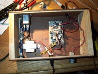
Well folks, I could'nt be happier today. I programmed the PIC and plugged it in and it worked on the first try. Talk about about a good feeling, that does not often happen for me.
Here is the code as it is now, and it works great..
Volume transition is smooth. I can't detect any noise from the digital pot changing volume at all.
Here is the code.
I am working on a REV 2 of the PCB. Stay tuned.
Talk about about a good feeling, that does not often happen for me. Here is the code as it is now, and it works great..
Volume transition is smooth. I can't detect any noise from the digital pot changing volume at all.
Here is the code.
I am working on a REV 2 of the PCB. Stay tuned.
Attachments
Russ White said:Well folks, I could'nt be happier today. I programmed the PIC and plugged it in and it worked on the first try.
Looks like you beat me to it...
nyways, congrats...
if your rev2 includes a remote and all that pizzaz, PUH-LEEZE look me up.
~m.
code tweaks
Ok, I have listened to this thing for two days now.
The only quirk I found was that every once in a while (say 1 out of 4 times) when I turn the power off and turned it back on only one channel would come up to the correct volume until I moved the pot. Well.. this revision of the code fixes it...
Now both channels come up correctly every time. 
Cheers!
Russ
Ok, I have listened to this thing for two days now.
The only quirk I found was that every once in a while (say 1 out of 4 times) when I turn the power off and turned it back on only one channel would come up to the correct volume until I moved the pot. Well.. this revision of the code fixes it...
Now both channels come up correctly every time.
Cheers!
Russ
Attachments
Question...
OK, this preamp sounds awesome, but I have noticed something odd.
When I turn off the pre, but leave the source on as well as the power amp a very small about of sign leaks through. This only happen when the power is off. Well this makes some sense looking at the PGA2311 datasheet it appears that at power off state the digital pot resets to about halfway.
Soo... I wonder how to prevent it.
I have a couple of theories:
1) make the impedance to the opamp(or rather from the PGA2311) lower by adding a resistor from the output of the volume control to GND.
2) Isolate the opamp from the PGA2311 by adding a 1K resistor in series with the output to the input of the AD8620.
3) both of the above.(the attached schematic is what I propose to do)
4) I could add a relay or a didgtally controlled switch, but I don't really want to do that.
Anyone got any ideas?
Other than that small quirk the thing sounds amazing.
Thanks,
Russ
Attachments
- Status
- This old topic is closed. If you want to reopen this topic, contact a moderator using the "Report Post" button.
- Home
- Amplifiers
- Headphone Systems
- Digitally controlled preamp/headphone amp