ok, i'm looking into makeing a tube-based amplifer for some sony mdr-v6 headphones. these are not the mdr-v600 headphones that many people don't like, but rather, the mdr-v6 which is supposedly the same as the new 7506 headphones.
in anycase, the headphones are listed as over 100dB @ 1mW and should thus be pretty efficient. they are also listed as 64ohm, and have a common signal group at the headphones. they are reported as being easy to drive and efficient.
ok, so i was thinking of making a tube amp for them, mainly just for fun. I was looking for a target of 50-100mW @ 64ohm, and stereo. this means i'd need signifigant biasing current for the output device right? approximately 40mA?
i was looking into maybe using a pair of 6v6gt pentodes for the output stages, 1 per channel. i was also looking into adding a voltage gain stage using a half of a 6sn7 per channel. i was planning on using 200V for my plate voltage for both the 6sn7 and the 6v6. i'm not entirely sure if i want a voltage gain stage or not.
then comes in the transformer. i was wondering what i should do for this section. i was looking into either a 125-0-125, 100mA, but that means i would have to choose between 100mA and ~200V or do 200mA and ~100V. or are these transformers rated in AC volts. the site with the transformer seems to indicate a DC value in typical useage.
here are my questions:
1.) 6sn7gt and 6v6gt -- good choices or not for this low power app.
2.) where can i find a cheaper transformer? i can't seem to find aything under $60 for the 400Vct+ @ 100mA nor anything under $30 for 200Vct @ 100mA
If you look on http://headwise.com/ you can find several good
headphone amps, you might look at the Morgan Jones clone of the EarMax amp. In paticular the power supply can be done realy
cheap.
Woody
headphone amps, you might look at the Morgan Jones clone of the EarMax amp. In paticular the power supply can be done realy
cheap.
Woody
hmm, i have seen the headwise site.
not sure were to get a 20V - 200V step up transformer...
in anycase i kinda wated to try 6v6 and 6sn7 for a kinda themed amp. sony v6 headphones, 6v6 output devices. well, you see what i mean...
is it possible to use the 6v6 below 250V? possibly at 100V?
not sure were to get a 20V - 200V step up transformer...
in anycase i kinda wated to try 6v6 and 6sn7 for a kinda themed amp. sony v6 headphones, 6v6 output devices. well, you see what i mean...
is it possible to use the 6v6 below 250V? possibly at 100V?
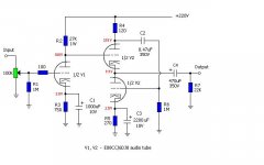
I've been trying to calculate how he came to 172V at the voltage divider with 27K resistor on the optimized Morgan Jones Headphone amp.
pic attached.
Please can someone show the calculations?
I understand how he calculated 218 Volts from 220 on the second leg but how did he come to 172V on the first part?
Vout = (R2/R4+R2) * Vin
27000/27120 * 220
Many thanks
pic attached.
Please can someone show the calculations?
I understand how he calculated 218 Volts from 220 on the second leg but how did he come to 172V on the first part?
Vout = (R2/R4+R2) * Vin
27000/27120 * 220
Many thanks
Attachments
theChris said:
in anycase, the headphones are listed as over 100dB @ 1mW and should thus be pretty efficient. they are also listed as 64ohm, and have a common signal group at the headphones. they are reported as being easy to drive and efficient.
ok, so i was thinking of making a tube amp for them, mainly just for fun. I was looking for a target of 50-100mW @ 64ohm, and stereo. this means i'd need signifigant biasing current for the output device right? approximately 40mA?
The mdr-v6 is rated at 106 dB for 1 mW. Therefore 2 mW gets you 109 dB, 4 mW gets you 112 dB, and 8 mW gets you 115 dB. That is subjectively *very loud*. So if you allow, say, four times that for some headroom then you should have plenty. In other words; 32 mW will be plenty for this application.
Now, what is the best way to provide 32 mW into 64 Ohms? My choice would be by transformer, but from the opening post I guess that you don’t want that. So you might just be left with the White Cathode Follower…
I've been trying to calculate how he came to 172V at the voltage divider with 27K resistor on the optimized Morgan Jones Headphone amp.
Brit, where do you see 172V?
The schematic shows 108V, and that's what it was in my built (roughly). After I converted my MJ to LED bias in the first stage (thread here on diyaudio) voltage at this point was rougly 140V which dropped back into place after I changed the 27K to 33K.
calculations (very quick): 27K at 4mA drops 108V. 220 - 108= 112. Of course slight variations apply.
Brit,
Are you using the 6N6p's in the first or second stage in your Aikido?
I built one using 6CG7 and 6H30 with a regulated supply (courtesy of Salas)...
Mind disclosing your cathode resistor values for the 6N6P?
The Morgan Jones headamp should be easily adapted to run 6N6P in the cathode follower...
though my Aikido sounds much better than my MJ did")
Are you using the 6N6p's in the first or second stage in your Aikido?
I built one using 6CG7 and 6H30 with a regulated supply (courtesy of Salas)...
Mind disclosing your cathode resistor values for the 6N6P?
The Morgan Jones headamp should be easily adapted to run 6N6P in the cathode follower...
though my Aikido sounds much better than my MJ did
Hi Stixx,
I'm using 5687 in the first stage and 6N6P in the second. I did have 6N1P's in the second but I needed less gain and actually preferred the 6N6P's. It sounds superb, and I'm running this into an old carver SS power amp with Klipsch speakers.
I'll look up the Cathode resistor values when I get back home. I think they were in the region of about 300 ohms but I'll have to verify that.
I did the wiring for the MJ last night and just realised I had the pins in reverse
I am wiring on a breadboard. Luckily I'm using small cable connectors to wire the components so I can interchange values easily without soldering anything.
Maybe I'll try the Aikido headphone configuration also.
The MJ project is my first point to point wiring job.
The Aikido was built using his circuit board.
Stixx,
Cathode resistors of Aikido with 5687/6N6P:
R2: 230
R11: 200
Now I have done some testing with my MJ circuit with 6N6P's. Opinions/advice would be appreciated.
Input tube(CF):
7mA idle (3.5V) with 468 ohm cathode resistor
100V at anode with R2 set at 25K
Upper output tube(WCF):
292 V at Anode with R4 set at 120 ohm
110 V between cathode and anode of bottom tube.
Bottom output tube of white cathode follower:
11 mA idle (3.3V) with 300 ohm cathode resistor
Conclusions?
B+too high?
Reduce R2?
Increase cathode resitors a little?
Thks
Since the original schematic was designed by Morgan Jones to run ECC88/6922 exclusively you are pretty much on your own to convert it to 6N6P... and I am not such an expert either .
Your first stage sounds OK to me though it is not a cathode follower but a "simple" grounded cathode input stage.
As stated on headwize the operation of the WCF depends on the balance of R2, R4 and R5... so using a different tube might lead to entirely different results...
Still you can experiment and check with your ears whether you like it or not. I would personally run the second stage some hotter (smaller R5) at a lower B+. Adjust R2 accordingly.
Maybe somebody else wants to chime in....or even Morgan Jones himself who is a quite a regular here on diyaudio
.Your first stage sounds OK to me though it is not a cathode follower but a "simple" grounded cathode input stage.
As stated on headwize the operation of the WCF depends on the balance of R2, R4 and R5... so using a different tube might lead to entirely different results...
Still you can experiment and check with your ears whether you like it or not. I would personally run the second stage some hotter (smaller R5) at a lower B+. Adjust R2 accordingly.
Maybe somebody else wants to chime in....or even Morgan Jones himself who is a quite a regular here on diyaudio
Hi Stixx,
yep my mistake stating CF.
Changed the values as suggested.
Now I'm getting 22mA on the WCF which is great.
and about 8 mA on the input stage.
B+ at WCF top anode is now at 250 V. I'm only running one channel.
I used PSUII to simulate another 20mA load (extra channel) and B+ should drop to about 220/230V.
Well this is the first headphone amp I've done and I'm quite impressed.
Sounds very nice indeed. Good separation, decent bass, and plenty of gain although I'm using small heaphones, not sure what impedance they are.
I want to try with a SS power supply. I'm currently using a 6X5GT built originally for the Aikido.
Think I will be building this one in a small chassis
But I also want to experiment with the 6N1P's and 6N2P's (less heater current but more gain on these 6N2P's).
Sounds very nice indeed. Good separation, decent bass, and plenty of gain although I'm using small heaphones, not sure what impedance they are.
I want to try with a SS power supply. I'm currently using a 6X5GT built originally for the Aikido.
Think I will be building this one in a small chassis
But I also want to experiment with the 6N1P's and 6N2P's (less heater current
but more gain on these 6N2P's).How many tubes?
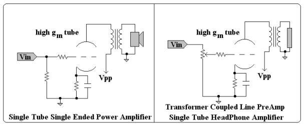
Headphones are efficient, just like you said. So, how many tubes per channel you need? One?theChris said:ok, i'm looking into makeing a tube-based amplifer for some sony mdr-v6 headphones. these are not the mdr-v600 headphones that many people don't like, but rather, the mdr-v6 which is supposedly the same as the new 7506 headphones.
in anycase, the headphones are listed as over 100dB @ 1mW and should thus be pretty efficient. they are also listed as 64ohm, and have a common signal group at the headphones. they are reported as being easy to drive and efficient.
But I also want to experiment with the 6N1P's and 6N2P's (less heater current but more gain on these 6N2P's).
Building the MJ with 6N1P would be the Bruce Bender headphone amp as can be found on Headwize...
- Status
- This old topic is closed. If you want to reopen this topic, contact a moderator using the "Report Post" button.
- Home
- Amplifiers
- Headphone Systems
- help on headphone amplifier