You're right! My bad. merlin el mago provided a measurement of 0.38H. I'll try that first, and also try with 0.48H.
Incidentally, where did you get your estimate of 0.48H for the secondary? Just curious...
__________________________
OK, did a quick pass with the secondary L changed to 0.38H.
Gain is about 2.4X. That's pretty much perfect for a headphone amp.
Distortion looks okay; very single-ended looking. The sim says 0.28% THD at 1V rms output.
Bandwidth is okay on the low end, -3dB at 20Hz. Looks fantastic on the high end; flat way out past 20kHz.
So maybe this is good?
_________________________
Quick pass with 0.48H secondary: Not a lot of change. Slightly higher gain, THD and relative harmonic levels stay close to the same.
_________________________
Last edited:
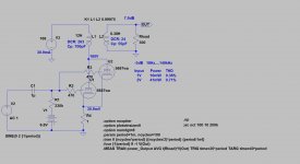
Also forgot the most important thing of OPT simulation: the coupling coefficient.
K: 1-(Lsp/Lp)
Lp: primary inductance
Lsp: leakage inductance. Measured primary inductance when secondary is shorted.
for example:
Lp: 20H
Lsp: 3mH
K: 0.99985
LTspice Spice directive: K L1 L2 0.99985
Lsp 20mH
It's a more realistic simulation.
The OPT's primary/secondary capacitance is estimated.
BTW if you use both halves, must to use grid stoppers for each grid (near to the pin).
Measured Cp primary & secondary:
Cp primary 2.7nF
Cp secondary 67nF
Last edited:
It's a more realistic simulation.
The OPT's primary/secondary capacitance is estimated.
BTW if you use both halves, must to use grid stoppers for each grid (near to the pin).
Can I ask what's the purpose of R4 1 ohm?
Measured Cp primary & secondary:
Cp primary 2.7nF
Cp secondary 67nF
I double-checked the measurement because I guess the secondary must be less value of capacitance than primary

Can I ask what's the purpose of R4 1 ohm?
Just as a way to show plate current for the two 5687 triodes. It's only 0.1R, so is so small it doesn't affect anything (not enough R to cause cathode degeneration).
Lsp 20mH
K: 1-(Lsp/Lp)
Lp: primary inductance
Lsp: leakage inductance. Measured primary inductance when secondary is shorted.
Lp: 12H
Lsp: 20mH
K: 0.99985
K = 1-(0.02/12)
= 1-(0.0016667)
= 0.99833...
LTspice Spice directive:
K L1 L2 0.99833
That will result in a lower high frequency f3. I'll run it again this evening, after I get home.
_______________________
I need to measure my Edcor XSE10-8K-50 OPTs and figure their coupling coefficient. I've been estimating it at 0.9985, just because it 'looked right.' HF f3 of about 40kHz or so.
--
It's a more realistic simulation.
The OPT's primary/secondary capacitance is estimated.
BTW if you use both halves, must to use grid stoppers for each grid (near to the pin).
Nice! Thanks for this.
You have some Spice directive entries in there that are new to me. I'll try them out. I especially like the .MEAS argument. I didn't know that existed.
You got THD numbers very similar to what I got. I'm using the the Ayumi N. 5687 model, which I think is different than the one you're using. If that's true, then I think we may have a reliable set of simulations going here.
I put the single grid stopper for simulation purposes only. Quick 'n dirty. I'd use separate grid stoppers for each triode in real life. Also, I'd use carbon composition (second choice carbon film) resistors for the grid stoppers, metal film for the grid leak resistors, or a good quality 100k or 50k log taper pot with a 1M grid leak resistor. But I wouldn't show all that in a provisional simulation.
Thank you.
What about the capacitance measurement?
Measured Cp primary & secondary:
Cp primary 2.7nF
Cp secondary 67nF
I don't know how to square those capacitance figures with the simulation. It's beyond my abilities in LTspice. Maybe euro21 can help with this?
Please could you simulate also with -3.3V grid 100V plate 14-15mA?
I did a quick run last night with Vg = -3.3V.
To get 15mA plate current, you'll need more like 110V on the plate.
I found that because of the slightly lower rp of the paralleled 5687s when run at lower Vp, the low frequency f3 was ever so slightly lower. THD was about 40% higher than at Vp=160V, Vg=-6.6V (about 0.4% for Vp=160 and Vg=-6.6V, vs. 0.6% at Vp=110V, Vg=-3.3V).
Long story short, there's not a huge difference between the two configurations. Just depends on the available B+ voltage.
--
merlin el mago said:What about the capacitance measurement?
Measured Cp primary & secondary:
Cp primary 2.7nF
Cp secondary 67nF
I guess primary must have high capacitance than secondary?
Are you sure the primary C is only 2.7nF, while the secondary C is much higher at 67nF?
Should that be 67pF (picoFarad)?
__________________
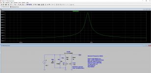
It's a holiday here today, so I had a few minutes to update the simulation.
Using the data available (admittedly not verified accurate):
1kHz 409mV rms input = 1V rms output into a 300 ohm load (3.3mW)
THD = 0.27%, 2nd harmonic predominating, 3rd harmonic -36dB from 2nd harmonic.
That's typically 'single-ended triode' looking. High THD, but practically all 2nd harmonic, higher order harmonics much lower to nonexistent. It should sound nice.
1kHz 1V rms input = 2.4V rms out into 300 ohms (19mW)
THD = 0.66%, 2nd harmonic still dominates, 3rd harmonic -72.5dB from input.
Frequency response:
-1dB 34.5Hz and 23.5kHz.
-3dB 17Hz
--
Any idea Bela?
If you own only multimeter with capacitance measurement ability, it's inappropriate to correct transformer measurements.
My LRC instrument (DER EE 5000) measuring frequency from 100Hz...100kHz.
Correct capacitance measurements is possible if the frequency is enough high (the leakage and main inductivity's impedance is enough high).
If you have sine generator and high impedance AC voltmeter the parasitic capacitance is measurable.
Parallel LC tank, Thomson formula.
LC circuit - Wikipedia
Sweep frequency, detect resonant dip, then from the frequency and given inductivity the Cip can be calculated.
Attachments
Hey guys,
Before use two tubes to change to PSE I tried the two bias with only one tube:
1/ Plate 150V B+ grid 6.6V (two batteries IKEA 3.3V)
2/ Plate 100V B+ grid 3.3V (one battery APR18650M1 - LiFePO4-Battery 3.3 V 1100 mAh - A123 Systems)
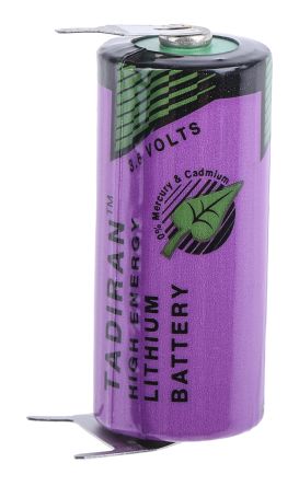
I prefer the SQ of 2nd bias 100V B+ & grid 3.3V. Now I want to try plate 100V B+ & grid 3.6V (Battery 2/3 AA Tabs Terminus(Terminal), Chloride of Tionilo-lithium, 3.6V, 1600mAh)
Apart from different bias, can be different SQ for different kind of batteries?
Before use two tubes to change to PSE I tried the two bias with only one tube:
1/ Plate 150V B+ grid 6.6V (two batteries IKEA 3.3V)
2/ Plate 100V B+ grid 3.3V (one battery APR18650M1 - LiFePO4-Battery 3.3 V 1100 mAh - A123 Systems)
I prefer the SQ of 2nd bias 100V B+ & grid 3.3V. Now I want to try plate 100V B+ & grid 3.6V (Battery 2/3 AA Tabs Terminus(Terminal), Chloride of Tionilo-lithium, 3.6V, 1600mAh)
Apart from different bias, can be different SQ for different kind of batteries?
Attachments
![WP_20180708_002[1].jpg](/community/data/attachments/625/625900-62502e093a01afcbc9afe4395d27b1ed.jpg)
Last edited:
Today change battery bias for two 2V green LEDs but I can set bot anode bias to 100V because there is a difference between the two triodes of 6V, I swapped the OPTs and still the difference, I know using two SSHV2 can solve the issue but can be that big difference in both triodes inside the same tube?
- Status
- This old topic is closed. If you want to reopen this topic, contact a moderator using the "Report Post" button.
- Home
- Amplifiers
- Headphone Systems
- 5687 headphone amp