Update 11/19/2014
The amp works great with the USB power coming from a PC and the audio source from and external device, like an ipod. But if both the USB power and the audio are coming from the same PC a ground loop can form, putting some digital noise on the output when run at high gain/volume. The solution is to use a small, cheap, cell phone USB charger like this "iessentials USB Wall Charger, 5Vdc 1amp" that goes for about $6 US dollars. The charger is rated for 110Vac-240Vac input so should work anywhere in the world with the appropriate prong adaptor. Amazon, Best Buy, Walmart.com, Staples, and several eBay vendors all have that same charger and they have it in a bunch of different colors. The amp works just fine with it, no digital noise at all when audio-sourced from the PC and zero AC hum.
Update 11/10/2014
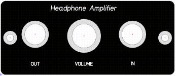
I've updated a few minor things on the V2.0 materials in post #2 for the coupling capacitor version of this project. I'm now calling this V2.1 to keep things straight. The two 4.7K load resistors added to the bottom of the board in the V2.0 build photo are now on the top of the board and added to the BOM. The rest of the changes are all with the text silkscreen to clarify part ID markings and text. I've also written a set of build instructions and and circuit description. I've posted the Front Panel Express CAD files for front and back panels, but they are untested.. use at your own risk.
The new V2.1 materials are at this this Google Drive link (V2.1 with coupling caps folder), including the schematic, layout, BOM, build instructions, case panels and Gerber files for making PC boards.
************************************************************************************************
Here is an over-engineered CMOY that is a take-off from posts in this thread. I didn't want to highjack matdogg's LME49723 thread any further!")
"
The V2.0 board in my last post in that thread is still on the way from fab, but the obvious thing from the circuit happened after some testing of V1.0. I completely forgot about leakage current in using large coupling caps which causes a rather large power-up "pop". I've switched to low leakage 470uF 6.3V caps (8uA of leakage vs. 500uA for the previous 470uF 6.3V caps) and increased the relay delay to an entire minute. The low leakage datasheet specs for the caps have the condition of valid after 1 minute. You can actually watch the DC offset voltage across the load decrease on a DMM (cap leakage current decrease) over a minute as the electrolyte does its thing. Less than one minute there is still enough cap leakage to cause a DC pop when connected. After one minute all is good.
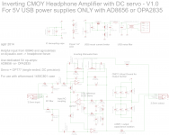
So here is a "real" CMOY using the two series virtual ground caps instead of output coupling caps to avoid that problem. As mentioned in that thread Chu's CMOY here returns the output to the series capacitor virtual ground and only at the end of the article mentions coupling caps as one solution to the DC unbalance - and hence output offset - that can happen with the virtual ground.
To get around that problem I've added a DC servo. The amplifier stage is still inverting to avoid common mode distortion, as sgrossklass noted in that thread, so the DC servo also has to be inverting. In this case it is a single servo using a single ended OP777 DC precision op amp. The servo not only integrates the DC at the virtual ground point over time, but does double-duty by acting as the 2.5Vdc reference for the inverting gain stages.
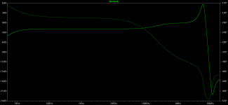
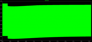
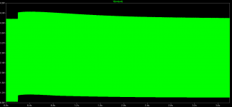
Below are the schematic, layout and LT spice runs. I've inserted a DC fault of 300mV in the gain stage output at 0.2 seconds. The transient plots show the servo stabilizes for either fault polarity in about 3 seconds. Unfortunately the AC plot has that nasty gain spike at 10MHz which would likely result in 10MHz oscillation - more work to be done there.
The amp works great with the USB power coming from a PC and the audio source from and external device, like an ipod. But if both the USB power and the audio are coming from the same PC a ground loop can form, putting some digital noise on the output when run at high gain/volume. The solution is to use a small, cheap, cell phone USB charger like this "iessentials USB Wall Charger, 5Vdc 1amp" that goes for about $6 US dollars. The charger is rated for 110Vac-240Vac input so should work anywhere in the world with the appropriate prong adaptor. Amazon, Best Buy, Walmart.com, Staples, and several eBay vendors all have that same charger and they have it in a bunch of different colors. The amp works just fine with it, no digital noise at all when audio-sourced from the PC and zero AC hum.
Update 11/10/2014
I've updated a few minor things on the V2.0 materials in post #2 for the coupling capacitor version of this project. I'm now calling this V2.1 to keep things straight. The two 4.7K load resistors added to the bottom of the board in the V2.0 build photo are now on the top of the board and added to the BOM. The rest of the changes are all with the text silkscreen to clarify part ID markings and text. I've also written a set of build instructions and and circuit description. I've posted the Front Panel Express CAD files for front and back panels, but they are untested.. use at your own risk.
The new V2.1 materials are at this this Google Drive link (V2.1 with coupling caps folder), including the schematic, layout, BOM, build instructions, case panels and Gerber files for making PC boards.
************************************************************************************************
Here is an over-engineered CMOY that is a take-off from posts in this thread. I didn't want to highjack matdogg's LME49723 thread any further!
"
The V2.0 board in my last post in that thread is still on the way from fab, but the obvious thing from the circuit happened after some testing of V1.0. I completely forgot about leakage current in using large coupling caps which causes a rather large power-up "pop". I've switched to low leakage 470uF 6.3V caps (8uA of leakage vs. 500uA for the previous 470uF 6.3V caps) and increased the relay delay to an entire minute. The low leakage datasheet specs for the caps have the condition of valid after 1 minute. You can actually watch the DC offset voltage across the load decrease on a DMM (cap leakage current decrease) over a minute as the electrolyte does its thing. Less than one minute there is still enough cap leakage to cause a DC pop when connected. After one minute all is good.
So here is a "real" CMOY using the two series virtual ground caps instead of output coupling caps to avoid that problem. As mentioned in that thread Chu's CMOY here returns the output to the series capacitor virtual ground and only at the end of the article mentions coupling caps as one solution to the DC unbalance - and hence output offset - that can happen with the virtual ground.
To get around that problem I've added a DC servo. The amplifier stage is still inverting to avoid common mode distortion, as sgrossklass noted in that thread, so the DC servo also has to be inverting. In this case it is a single servo using a single ended OP777 DC precision op amp. The servo not only integrates the DC at the virtual ground point over time, but does double-duty by acting as the 2.5Vdc reference for the inverting gain stages.
Below are the schematic, layout and LT spice runs. I've inserted a DC fault of 300mV in the gain stage output at 0.2 seconds. The transient plots show the servo stabilizes for either fault polarity in about 3 seconds. Unfortunately the AC plot has that nasty gain spike at 10MHz which would likely result in 10MHz oscillation - more work to be done there.
Attachments
-
Inverting CMOY with inverting DC servo schematic V1.0.pdf30.9 KB · Views: 73
-
 Inverting CMOY with inverting DC servo LTspice AC plot V1.0.png9.9 KB · Views: 226
 -
 Inverting CMOY with inverting DC servo LTspice -300mV fault V1.0.png6.9 KB · Views: 216
 -
 Inverting CMOY with inverting DC servo LTspice 300mV fault V1.0.png6.7 KB · Views: 234
 -
Inverting CMOY with inverting DC servo Spice schematic V1.0.pdf21.5 KB · Views: 58
-
 Inverting CMOY with inverting DC servo layout V1.0.png425.2 KB · Views: 307
 -
 Inverting CMOY with inverting DC servo schematic V1.0.png87.3 KB · Views: 287
 -
Inverting CMOY with inverting DC servo layout V1.0.pdf205.7 KB · Views: 49
Last edited:
V2.0 of coupling cap version works - Gerbers posted
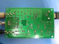
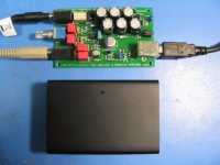
I finally received the V2.0 PCB of the output coupling capacitor version of this inverting CMOY 5V USB amp project. It works! I've posted the Gerbers below along with the BOM, layout, schematic, etc. in case anyone wants to mess around with building one.
Even though the 470uF low-leakage coupling cap datasheet says 8uA after 1 minute of applied voltage, I found experimentally that 30 seconds is enough time to eliminate any DC turn-on pop on power-up. So the headphone relay is set for about 35 seconds turn-on delay with the 1.5M resistor and 22uF capacitor. Still a tiny turn-off pop but I don't have a solution for that yet.
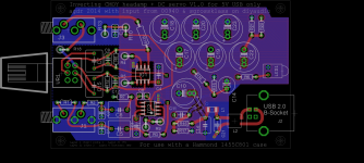
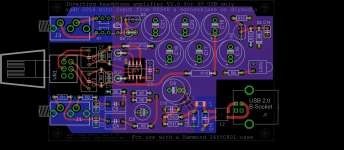
The board is 4 layer. At Seeed Studio the minimum fabrication quantity of 5 comes to $40 and shipping is another $10, so around $5 a board. Not bad for 4 layers!
95% of it is through hole. The common mode choke, ferrite bead, and one part on the back of the board (inrush delay mosfet) are SMD. Also on the back are two 4.7K 1/8W output load resistors from each output (before the relay) to ground to allow current to immediately flow though the low-leakage caps on power-up and the barrier to form. I didn't realize they were needed until testing and the switch to low-leakage coupling caps.
The electrolytic cap positions have holes for both 3.5mm and 5mm lead spacing since there are several choices in both at Mouser and Digikey.
The ground plane is removed under the AD8656 chip and under the feedback network due to comments in the AD8656 datasheet about the importance of reducing capacitance from the input pins to ground plane (prevent oscillations).
I finally received the V2.0 PCB of the output coupling capacitor version of this inverting CMOY 5V USB amp project. It works! I've posted the Gerbers below along with the BOM, layout, schematic, etc. in case anyone wants to mess around with building one.
Even though the 470uF low-leakage coupling cap datasheet says 8uA after 1 minute of applied voltage, I found experimentally that 30 seconds is enough time to eliminate any DC turn-on pop on power-up. So the headphone relay is set for about 35 seconds turn-on delay with the 1.5M resistor and 22uF capacitor. Still a tiny turn-off pop but I don't have a solution for that yet.
The board is 4 layer. At Seeed Studio the minimum fabrication quantity of 5 comes to $40 and shipping is another $10, so around $5 a board. Not bad for 4 layers!
95% of it is through hole. The common mode choke, ferrite bead, and one part on the back of the board (inrush delay mosfet) are SMD. Also on the back are two 4.7K 1/8W output load resistors from each output (before the relay) to ground to allow current to immediately flow though the low-leakage caps on power-up and the barrier to form. I didn't realize they were needed until testing and the switch to low-leakage coupling caps.
The electrolytic cap positions have holes for both 3.5mm and 5mm lead spacing since there are several choices in both at Mouser and Digikey.
The ground plane is removed under the AD8656 chip and under the feedback network due to comments in the AD8656 datasheet about the importance of reducing capacitance from the input pins to ground plane (prevent oscillations).
Attachments
-
 front panel.PNG23.7 KB · Views: 55
 -
Inverting CMOY 10_26_2014 V2.0.zip82.8 KB · Views: 46
-
Inverting CMOY BOM V2.0 5.zip13.4 KB · Views: 38
-
schematic.pdf30.8 KB · Views: 57
-
layout.pdf207.8 KB · Views: 51
-
 layout.png510.2 KB · Views: 87
 -
 schematic.png68.1 KB · Views: 98
 -
 IMG_3122.JPG191.5 KB · Views: 94
 -
 IMG_3121.JPG173.8 KB · Views: 98
 -
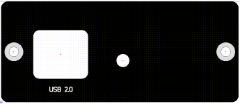 rear panel.PNG12.5 KB · Views: 44
Last edited:
- Status
- This old topic is closed. If you want to reopen this topic, contact a moderator using the "Report Post" button.