Hifiman, out of China. They have made orthos for a few years now with the HE-6 considered top headphones but requiring a lot of power.
The DIY amp does great with them and this phone is so transparent that it changes with whatever you are driving it with so what you use, needs to be good.
I have a few different HeadPhones and one of them is the HiFiMan HD500. Very transparent and revealing and with this HP amp, it is stunning.
I had a BenchMark DAC 1 with built in HP amp. When it was time to upgrade to the DAC 2 model, I got the one without HP amp as this DIY'er is much better.
[IMHO]
THx-RNMarsh
Last edited:
I have a few different HeadPhones and one of them is the HiFiMan HD500. Very transparent and revealing and with this HP amp, it is stunning.
I had a BenchMark DAC 1 with built in HP amp. When it was time to upgrade to the DAC 2 model, I got the one without HP amp as this DIY'er is much better.
[IMHO]
THx-RNMarsh
After about 200 hours the HE start to really break in. I have the HE500, HE560, HE-6 and these from the Hifiman line. I just read a comparison someone did who had the Orpheus and Omega 2 for a month. He said the HE1000 are like the best of both.
I can tell you that the HE1000 are better than anything I have or have heard.
How can I get an HE1000 to listen to with this DIY HP amp? Short of paying MSRP.
I noticed their Z is 30-40 Ohms.
-RNM
There are beta testers.
I have changed over to Whiplash TWau cable running DoP to the Chord Hugo to the RM DIY amp. What sound! I actually don't enjoy getting goosebumps with this you can't help it.
These are not headphones in the traditional sense. They sit on your head but are neither headphones or speakers in sound. A product that has actually transcended all others, amazing.
Richard I did PM you the other day.
These are not headphones in the traditional sense. They sit on your head but are neither headphones or speakers in sound. A product that has actually transcended all others, amazing.
Richard I did PM you the other day.
 .
.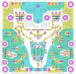
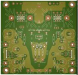
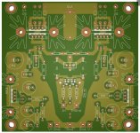
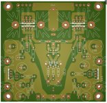
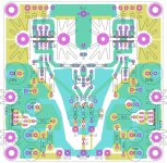
V3
- output transistors footprint marked, on top for BCE, on bottom for ECB
- resistors R11/R13 & R12/R14 change connection point when you change output transistors pinout BCE <> ECB, marked on board
Regarding input JFET pair, board is compatible with both THT&SMD input JFETs.
THT JFETs can be both SGD&GSD with minimal bending.
SMD JFETs are SOT-23 Fairchild MMBF5457/MMBF5460 pinout.
In all cases, presumed Source & Drain are interchangeable.
For SMD SOT-23 JFETs , this heat sink is planned:
50pcs 13x13x11mm High Quality Aluminum Heat Sink for Chip Electronic H36 | eBay
For heat sink mounting, M2 holes added (1.6 mm drill) distance center to center 15mm.

This board have similar layout to headamp board based on F5:
http://www.diyaudio.com/forums/pass-labs/271926-f5-headamp-19.html#post4352656
- output transistors footprint marked, on top for BCE, on bottom for ECB
- resistors R11/R13 & R12/R14 change connection point when you change output transistors pinout BCE <> ECB, marked on board
Regarding input JFET pair, board is compatible with both THT&SMD input JFETs.
THT JFETs can be both SGD&GSD with minimal bending.
SMD JFETs are SOT-23 Fairchild MMBF5457/MMBF5460 pinout.
In all cases, presumed Source & Drain are interchangeable.
For SMD SOT-23 JFETs , this heat sink is planned:
50pcs 13x13x11mm High Quality Aluminum Heat Sink for Chip Electronic H36 | eBay
For heat sink mounting, M2 holes added (1.6 mm drill) distance center to center 15mm.
This board have similar layout to headamp board based on F5:
http://www.diyaudio.com/forums/pass-labs/271926-f5-headamp-19.html#post4352656
Attachments
Last edited:
Hi Mr. Marsh, thanks for your comment.
I hope to complete amp sometime in autumn, here is summertime now , I hope to complete parts and board until then.
Of course I will share with others, I'll order my PCB from dirtyPCBs, one of the chinese PCB manufacturing sites with really low prices, and they have option to share design with others, so it's super easy for me, just click and forget.
This PCB is 10x10 and their price is 25$ for 10+-2 pcs (protopack) including worldwide shipping, hard to beat. (ordered 5 times at dirty, 4 times get 12 pcs, one time get 11 pcs)
My last order is RAW DC companion board for this amp and F5 headamp: Raw DC@Dirty PCBs
BR, Sika
I hope to complete amp sometime in autumn, here is summertime now
, I hope to complete parts and board until then.Of course I will share with others, I'll order my PCB from dirtyPCBs, one of the chinese PCB manufacturing sites with really low prices, and they have option to share design with others, so it's super easy for me, just click and forget
.This PCB is 10x10 and their price is 25$ for 10+-2 pcs (protopack) including worldwide shipping, hard to beat. (ordered 5 times at dirty, 4 times get 12 pcs, one time get 11 pcs)
My last order is RAW DC companion board for this amp and F5 headamp: Raw DC@Dirty PCBs
BR, Sika
Hi guys, I've just bought the PCB & parts from Jack & awaiting for it's arrival. In the meantime, I've purchased the Marsh head amp article here: Linear Audio | your tech audio resource
On page 37, the final schematic R3 & R4 has no specified value, can anyone double check your copy, maybe my pdf copy is corrupted or something...
cheers, lloop9
On page 37, the final schematic R3 & R4 has no specified value, can anyone double check your copy, maybe my pdf copy is corrupted or something...
cheers, lloop9
You don't need much in the way of heat-sinking the output transistors. Despite Dr. Marsh's protestations, I have mine affixed to the bottom of the chassis.
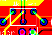
it would be nice to allow for both types of Bourns potentiometers -- in line and offset. See pic
if you have to regulate (as Dick has mentioned, more juice is better, so you are trading off sound quality vs the regulator's overhead), I would much prefer you use LT1963A and LT3015.
it would be nice to allow for both types of Bourns potentiometers -- in line and offset. See pic
if you have to regulate (as Dick has mentioned, more juice is better, so you are trading off sound quality vs the regulator's overhead), I would much prefer you use LT1963A and LT3015.
Attachments
R4 is the same value as R5 and R3 is the same as R6. Contact Jan and I'm sure he will get you a clean copy of that page.
This for the advice, I've already contacted Jan.
If the reference is to page 37, figure 8, then the above advise is invalid. There is no 'R6', R5 is 1K to ground, don't think R4 should be this value. There is another labeling error in the schematic, there are 2 R3's, one below J1 and one below J2.
If I read it correctly, P1 is there to balance the unmatching of J1 and J2. The unknown J3 and J4 can be something like 50R each. Remember they in are in series to each side of P1 anyway. FWIW, Jack's PCB labels both as 51R. In theory, if you have perfectly matched J1 and J2, then you can use 2 perfectly matched 500R for R3 and R4 and get rid of (jumpered) P1
If I read it correctly, P1 is there to balance the unmatching of J1 and J2. The unknown J3 and J4 can be something like 50R each. Remember they in are in series to each side of P1 anyway. FWIW, Jack's PCB labels both as 51R. In theory, if you have perfectly matched J1 and J2, then you can use 2 perfectly matched 500R for R3 and R4 and get rid of (jumpered) P1
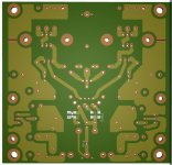
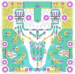
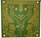
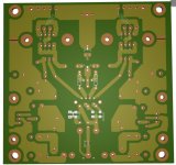
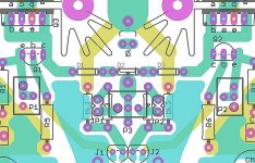
v4
- changed trimmer footprint to support offset
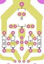
- added optional RF1, RF2 feedback resistors ala F5
- added jumpers JP1, JP2 between JFET source resistors and trimmer. For normal operation needs to be closed/shorted
Motive for adding alternative feedback resistors & jumpers is potential operation of this circuit in balanced mode. In balanced mode is possible to interconnect feedback networks of two halves on different ways (topologically).
This changes open that possibilities.
Anyhow, for standard operation, do not populate RF1&RF2, jump JP1&JP2, result original schematics.
BR, Sika
- changed trimmer footprint to support offset
- added optional RF1, RF2 feedback resistors ala F5
- added jumpers JP1, JP2 between JFET source resistors and trimmer. For normal operation needs to be closed/shorted
Motive for adding alternative feedback resistors & jumpers is potential operation of this circuit in balanced mode. In balanced mode is possible to interconnect feedback networks of two halves on different ways (topologically).
This changes open that possibilities.
Anyhow, for standard operation, do not populate RF1&RF2, jump JP1&JP2, result original schematics.
BR, Sika
Attachments
- Home
- Amplifiers
- Headphone Systems
- Marsh headphone amp from Linear Audio