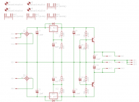
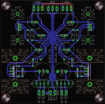
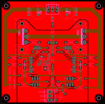
Final versions of my supply board as well as my no thump board.
Note, the schematic might show a LM7809 regulator on the HANTB MKI, however the exact regulator used depends on your ac voltage as well as the relay used.
I have not ordered them yet, but will do so this weekend.
Boards should be done and tested in a month or so and I do not expect any issues since this is just improved versions of earlier boards.
Attachments
In general 32 Ohm headphones do not need alot of voltage across them, but they do like some current reserves. On the other hand 600 Ohm headphones do need alot more voltage across them, but do not really need that much current.
I personally feel that +/- 12V and a few hundered mA of bias current is a good balance. Besides, higher bias gives lower distortion.
I also like to oversize things and using a pair of big 7 A devices does not cost much more than the significantly smaller and less powerful 2sj76, 2sk213 Lateral FET's. Also, the 2sj76, 2sk213 Lateral FET's are hard to come by, while I on the other hand have a good source of the 2SK1058/2SJ162 Lateral FET's from a supplier where I can get them for about 5$ a piece.
With regards to stability I have already considered both an output resistor or an output inductor//resistor but decided that increasing the compensation caps would be far simpler and work just as good.
Bottom line is that it works and sounds great as well.
My own personal goals for this headamp have been more than met.")
Nice clean circuit with good choise of parts and thier use = excellent performance.
-RNM
Last edited:
This project is done.
Sort of done.
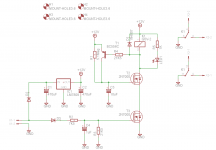
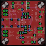
Made an improved(I hope) amplifier board.
Oops.
Nothing to see here, just move along.

Attachments
Last edited:
After checking the specs of the R&S UPL Audio Analyzer I think I might be redoing the measurements some day. It only goes up to 110kHz, but has lower generator distortion, higher dynamic range and the noise floor is between -120 and -140.
Seems you've moved on, but perhaps some more here.
Design is very much Borbely; and thus Hafler with simplified jfet input stage of XL280, and simplified remaining stages of DH220.
As such I would expect a magnitude of order better performance from what you have here.
In posted measurements analyzer/generator are limiting, but no need for R&S type instrumentation. Many sound cards are in this performance range. I use E-MU 0404 USB. Full scale sine out, output volume set to 1.3v rms (not quite max) is looped back to input (no mic gain). Result is normalized and displayed:

Sound card is connected to clone of Hafler XL280 with 8ohm resistive load adjusted to 10watts. Output is captured via Fostex FR2, which had built in adjustable padding. FR2 digital out slaves E-MU clock, results recorded, normalized and displayed:

R9 bridging jfets may be fully expanded as is Borbely designs and XL280 allowing both trim of current and DC offset. I didn't understand/see/figure this out until after project completed. Hand matched resistor in jfet bridge gave me 4mv DC. I also learned just how temperature sensitive jfets are. Lightly blowing on any of them pushes DC all over the place. Retrospectively I would of tightened up my layout and gotten four jfets on a small sink for thermal stability.
Thanks for the thread.
Andrew
- Status
- This old topic is closed. If you want to reopen this topic, contact a moderator using the "Report Post" button.