1. The boards will accept up 13mm dia capacitors for C1 C2. The lead spacing is 5 mm. If you look at the boards you can see I think that there is no room for larger ones. The pads have thermal isolation from the ground plane, but nonetheless this does suck up a fair bit of heat so a relatively powerful soldering iron is recommended.
2. Thanks for your comments re. the manual, I will endeavor to make some updates.
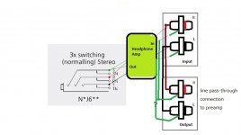
3. For the preamp connection, it depends what signal you want to feed to the preamp but I will assume it is the straight pass-through connection from the RCA inputs of the JMO2. In that case you cannot make it switch as you connect the headphones, at least not with the usual switched headphone jack as these can only switch the routing of the headphone amp output between the headphones and another output.
2. Thanks for your comments re. the manual, I will endeavor to make some updates.
3. For the preamp connection, it depends what signal you want to feed to the preamp but I will assume it is the straight pass-through connection from the RCA inputs of the JMO2. In that case you cannot make it switch as you connect the headphones, at least not with the usual switched headphone jack as these can only switch the routing of the headphone amp output between the headphones and another output.
Attachments
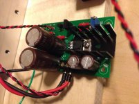
I'm just trying to advice to some hobbyists who might be interested to use this "best in today's market" caps. I used 10mm diameter Elna Silmic II RFS 100uFs 35V. The challenge was to bent legs of these caps since they have 5 mm leg spacing and PCB has 3.5 mm vias. Elna Silmic II RFS 1000uF 35V with 18mm dia used there too and PCB has 5 mm when caps 7.5 mm leg spacing. Honestly, I see no problem to drop such big caps there. There is enough space. Would be nice to have additional vias to support 5 and 7.5 mm legs. Please see attached close picture.
Thank you for RCA Output connection advice. I'll try it and in worse case, I'll add some toggle switch (on/off).
Thank you for RCA Output connection advice. I'll try it and in worse case, I'll add some toggle switch (on/off).
Attachments
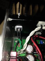
In did, my amp performance increased when I started to use AS-1220 (in my case, it is 20.8V secondary out).
It added more transparency to sound.
So, I have 24,7V in to BIB and 16V out. 8.7V delta vs. 6V with my old AS-1218. What is left, it is just to box it....
I'll send pictures soon.
BTW, AKG K701 is on it way to my home. Will try them next weekend.
It added more transparency to sound.
So, I have 24,7V in to BIB and 16V out. 8.7V delta vs. 6V with my old AS-1218. What is left, it is just to box it....
I'll send pictures soon.
BTW, AKG K701 is on it way to my home. Will try them next weekend.
In did, my amp performance increased when I started to use AS-1220 (in my case, it is 20.8V secondary out).
It added more transparency to sound.
So, I have 24,7V in to BIB and 16V out. 8.7V delta vs. 6V with my old AS-1218
Higher Vds is good for the ccs mosfet ... it lowers parasitic capacitance and ameliorates frequency spec.
ideally a Vds of +15v would be even better but temp would be a major issue.
Higher Vds is good for the ccs mosfet ... it lowers parasitic capacitance and ameliorates frequency spec.
ideally a Vds of +15v would be even better but temp would be a major issue.
I remember you mentioned that you set your amp voltage to 15v (not 16V).
Here is my question to you and Richard:
Is any impact to run that amp with +15V instead of +16V?
If no issue, I'll try it. At that case my Delta V will be very close to 10V on BIB.
The circuit operates relatively independently of the V+ voltage, and the thermals can be controlled via the trim potentiometer. You should be able to run it at 20-25 V with no problems, as long as you lower the bias current a little.
I actually would like to lower it from 16V to 15V.
So, should be no issue?
In addition, my R7 is getting to about 67 deg C (kind of really hot).
Should I lower the trimmer? It is set to 5.5v across R7 now.
If to adjust, then to what value?
Thank you.
R7 well get hot but this resistor is designed to run hot. It's a 2 W resistor dissipating (5.5 V * 5.5 V) / 30 ohm = 1 W.
Sorry I misread your earlier post. Yes you can run at 15 V also with no problems. As you lower the voltage (but adjusting the trimmer to keep the same 5.5 V on R7), you are lowering the voltage headroom available before clipping, basically, which is (roughly!) power supply voltage - 9 V. So 16 V gives you about 7 V max p-p output, while 12 V would only leave you with 3 V p-p. For this reason I don't think it would be a good idea to go below 12-13 V.
Sorry I misread your earlier post. Yes you can run at 15 V also with no problems. As you lower the voltage (but adjusting the trimmer to keep the same 5.5 V on R7), you are lowering the voltage headroom available before clipping, basically, which is (roughly!) power supply voltage - 9 V. So 16 V gives you about 7 V max p-p output, while 12 V would only leave you with 3 V p-p. For this reason I don't think it would be a good idea to go below 12-13 V.
R7 well get hot but this resistor is designed to run hot. It's a 2 W resistor dissipating (5.5 V * 5.5 V) / 30 ohm = 1 W.
Sorry I misread your earlier post. Yes you can run at 15 V also with no problems. As you lower the voltage (but adjusting the trimmer to keep the same 5.5 V on R7), you are lowering the voltage headroom available before clipping, basically, which is (roughly!) power supply voltage - 9 V. So 16 V gives you about 7 V max p-p output, while 12 V would only leave you with 3 V p-p. For this reason I don't think it would be a good idea to go below 12-13 V.
Thank you. I'll try and let you know about my listening impression.
Sure, that's an ideal use for that part. Expensive though, and of course there is no objective need to use a 30 W resistor to dissipate 1 W of power...
Thank you.
They are not cheap and that is through.
Although, they are capable to run 30W with huge heat-sink.
With out heat sink they can run about 2-3W.
Hi Richard,
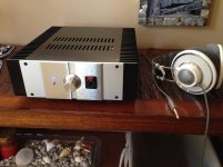
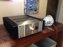
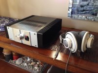
Finally, I finished my amp. Just received my front panel from local CNC machine shop...
It is an amazing project and I enjoined it very much and every step of it.
Please see my final setup pictures.
It is sounds amazing on both, my CD player and on my Turntable.
Thank you a lot.
BTW, I used Caddock MP930 resistor for R7 and also attached to the heat sink.
Also, my personal appreciation to all who help me to buid it:
Salas (BIB Voltage regulator)
Kentoken (K-Multi)
Billlouey (Raw DC and snubber calculations)
all others....
Thank you all.
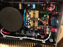
Attachments
Last edited:
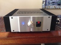
"Very nice" doesn't even remotely cut it. That looks frickin' amazing!
Thank you.
")
- Status
- This old topic is closed. If you want to reopen this topic, contact a moderator using the "Report Post" button.
- Home
- Amplifiers
- Headphone Systems
- J-Mo Mk II headphone amplifier