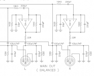
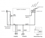
In the simplest form you built this SE->bal converter (copied from a Bryston preamp) and put the four Sapphire where the XLR jack is shown. In front the the converter you need a line buffer (since the converter circuit only has a 10k input impedance), and in front of that your volume control. If you don't need a volume control then the inputs can feed the converter directly.
Alternatively you could built it as literally a "heaphone amplifier" and drive it with a separate line-level preamplifier.
Alternatively you could built it as literally a "heaphone amplifier" and drive it with a separate line-level preamplifier.
Attachments
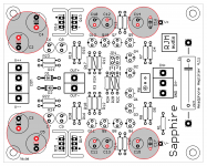
Sapphire 4.1z / preview
I'm out of 4.1t boards so I figured I'd do a final touch respin to make some cosmetic changes to the layout. 4.1z changes very little, nothing of practical merit worth mentioning in fact.
The BOM now includes the high power configurations.
I'm out of 4.1t boards so I figured I'd do a final touch respin to make some cosmetic changes to the layout. 4.1z changes very little, nothing of practical merit worth mentioning in fact.
The BOM now includes the high power configurations.
Attachments
Hey Richard,
My knowledge in circuitry is very limited so the answer may be obvious, but I was curious at the differences between the Sapphire and the AMB CKKIII ?
I have built the Sapphire v4 and I'm loving it so far, but I have now got the itch and was thinking of building something small for the office desk.
Reading the description of the CKKII, it sounds pretty similar to the description of the Sapphire.
From the website: "It was designed with an emphasis on maintaining simplicity in the signal path, and utilizes an all-discrete, fully-complementary topology featuring a JFET input stage, current-mirror VAS (voltage gain stage), Sziklai complementary feedback pair (CFP) output stage, and no global negative feedback."
The Cavalli-Kan Kumisa III stereo headphone amplifier
While the topology is superficially similar, the execution is very different. Conceptually it feels to more like a mini power amplifier, whereas the Sapphire might be better thought of as a bulked up preamp circuit perhaps.
I don't really have an opinion one way or another, except to note that Q2 and Q3 being jfets opens you up to the usual jfet issues of p/n parameter missmatch and thermal drift. How much that practically affects the circuit I'm not sure.
I don't really have an opinion one way or another, except to note that Q2 and Q3 being jfets opens you up to the usual jfet issues of p/n parameter missmatch and thermal drift. How much that practically affects the circuit I'm not sure.
Hello Richard,
Glad to see your latest option on a higher output Sapphire. I have both the V-Moda M100 (32ohms) and AKG K712 (62ohms). I think the 150ma bias current configuration is my best setting.
I really appreciate your effort in keeping the Sapphire HA lively with these options.
Henry
Glad to see your latest option on a higher output Sapphire. I have both the V-Moda M100 (32ohms) and AKG K712 (62ohms). I think the 150ma bias current configuration is my best setting.
I really appreciate your effort in keeping the Sapphire HA lively with these options.
Henry
Greetings
Just starting to collect BOM for one of these - very excited. Relatively new to headphone amps and over the last 6months have built a Starving Student and O2. Been reading through the thread to learn about the circuit and peoples experiences with various part selections.
I've not so far in my reading seen much discussion of resistor selection (other than values). Are there any particular resistor positions that most benefit from "higher quality" components?
I notice very precise values like 221r and 4.75r >> considering +/- tolerances I presume rounding to the nearest 10 or 1/10 would be ok if sourcing these exact values is difficult for me?
Thanks in advance. Looking forward to gaining my Sapphire membership.
Last edited:
One metal film resistor is as good as any other. Vishay-Dale are good, KOA Speer are fine, Takman REY are nice too.
The "precise" values are given only because we are buying 1% resistors and those are the standard part values for 1% resistors. If we were using 5% resistors, we would select 220 and 4.7 ohms for example. There is no difference between 4.75 and 4.7 ohms so far as the circuit operation is concerned.
*****
10% tolerance:
10 12 15 18 22 27 33 39 47 56 68 82
5% tolerance:
10 11 12 13 15 16 18 20 22 24 27 30
33 36 39 43 47 51 56 62 68 75 82 91
1% tolerance:
10.0 10.2 10.5 10.7 11.0 11.3 11.5 11.8 12.1 12.4 12.7 13.0
13.3 13.7 14.0 14.3 14.7 15.0 15.4 15.8 16.2 16.5 16.9 17.4
17.8 18.2 18.7 19.1 19.6 20.0 20.5 21.0 21.5 22.1 22.6 23.2
23.7 24.3 24.9 25.5 26.1 26.7 27.4 28.0 28.7 28.4 30.1 30.9
31.6 32.4 33.2 34.0 34.8 35.7 36.5 37.4 38.3 39.2 40.2 41.2
42.2 43.2 44.2 45.3 46.4 47.5 48.7 49.9 51.1 52.3 53.6 54.9
56.2 57.6 59.0 60.4 61.9 63.4 64.9 66.5 68.1 69.8 71.5 73.2
75.0 76.8 78.7 80.6 82.5 84.5 86.6 88.7 90.9 93.1 95.3 97.6
If they fit on the board you can use the 1W metal oxide. If you use 2.21 ohms the bias current will be lower, about 75 mA.
There is no particular restriction for type, though since there is no trimming of the bias current built into the design it's best to use 1% tolerance if you want the bias between the two channels to be closely matched.
There is no particular restriction for type, though since there is no trimming of the bias current built into the design it's best to use 1% tolerance if you want the bias between the two channels to be closely matched.
Hello Richard,
Just about finished with the Sapphire 4 configured close loop, 150ma max bias current, gain of 25, and both channel's dc offset is stable under 5mv.
Trying to get the most minute audible background noise is sitting powered on. Input is shorted, output is to my V-Moda M100 headphone, and the slightest noise can be heard. Not sure if it is a buzz or hum.
I think my improvement could be a better grounding scheme. I am trying to sort through our forum for a best scheme in my case, thought I short-cut posting for a answer/recommendation from you. The HA is in a metal case, everything (input, output jacks, power supply) is floating. The AC ground is wired to the chassis.
Thank for reading,
Henry
Photo please.
If everything is floating as you say, then wire the Sapphire GND pads to the chassis, bare metal, lock tooth washer at the chassis end.
In my Sapphire, the residual noise spikes was pickup internally between the power supply charging pulse currents and, I think, the input coupling capacitors. This is not audible, but visible above the measured white noise baseline. It depended on how well shielded the transformers were, and to the type (physical size?) of film capacitor.
One additional important point, more current means larger ripple voltages for the same value of filter capacitance. Reducing the resistance R23,R24 from 1k to 221R, needed to handle the higher current, increases ripple also. According to my simulation the 120 Hz ripple on the output rises to -100 dB for the 150 mA configuration, compared to under -130 dB for the default BOM. Ah, yes, there is no free lunch! -100 dB is likely to be low level just audible. Increasing the filter capacitance from 1000 uF to 3000 uF drops that to -110 dB which is probably inaudible. If you want to go further, up to 10,000 uF on V++/V--, and up to 1000 uF for all the 100 uF caps.
I'll update the BOM with a note to this effect.
pcb-sapphire-41t3-bom (high current supplemental)
Unfortunately to bump up the capacitance means using bigger packages than fit on the board outline. The mod may end up unsightly.
The capacitance values are a rough guide and a compromise. The bring the ripple down to the same value as the standard version before R23,R24 are changed, after everything is said and done the output ripple will still be 6-12 dB or so higher. To actually get par the capacitance would have to be doubled again for the 75 mA build, and made four times larger again for the 150 mA build, increasing out to that level would bring it's own set of issues.
Attachments
Detailed answer, thank you Richard. Yes, I have a star ground with everything tied (wires from out-, in-, input grd, output grd, potentiometer grd) together. Will try bolting the star to the chassis. My AC grd wire is to the chassis already.
I should be content with the result of your Sapphire 4. The background noise I am talking about is likely the residual inherent you describe. Of the 3 dynamic headphones, only the V-Moda M100 @25db gain detects the 'noise'. Sennheiser 700 (150ohms) @30db gain and AKG K712 (62ohms) @30db gain are silent.
I should consider my build completed with the exception of 41t3 bom bonus recommendations. Again, thank you so much for your design. Henry
I have a star ground with everything tied (wires from out-, in-, input grd, output grd, potentiometer grd) together. Will try bolting the star to the chassis. My AC grd wire is to the chassis already.
I have not found any iterations of the Sapphire to be especially sensitive to grounding. Note that you should not connect OUT-, IN-, etc. to a star ground or to the chassis yourself. These signals are connected to each other and to COM/GND already internally on the board (there is already a star ground if you will), the only connection you need to make is from the chassis to GND.
Attachments
Last edited:

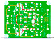
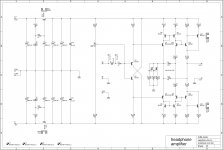
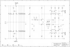
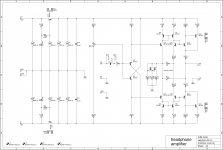
That was maybe a mistake to upload the schematic. Please use the BOM for the parts values making whatever adjustments for bias current, gain, and feedback configuration you need. Attached shows the high current version.
C2,3 are 18 mm cans with 7.5 mm lead spacing. In Nichicon KW/FW series the maximum is 6800/25. C4-9 are 10 mm cans with 5 mm spacing, the largest capacitance value being 1000/25.
C2,3 are 18 mm cans with 7.5 mm lead spacing. In Nichicon KW/FW series the maximum is 6800/25. C4-9 are 10 mm cans with 5 mm spacing, the largest capacitance value being 1000/25.
Attachments
- Home
- Amplifiers
- Headphone Systems
- RJM Audio Sapphire Desktop Headphone Amplifier