I've sometimes been asked to provide an "official" RJM Audio logo - seems to be an uptick in interest recently. Feel free to use. The new version I use for my diyaudio avatar is created from the vector text in Eagle, the older one pictured is just Century Gothic text in a square border. "audio" is lowercase in the logo, capitalized otherwise.
Attachments
Last edited:
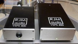
An excellent demonstration of the advantages to using an oversize enclosure.
In addition to providing plenty of separation between the power supply and input signals, all the hardware can be placed in the ideal position without compromise.
It's the most formal component layout and frankly still the best: viewed from the backplate, input signal far left, power supply on the far right, input to output sections moving left to right.
Hello, just wonder how large the enclosure is required? What's the dimension?
Hello, just wonder how large the enclosure is required? What's the dimension?
Richard could better answer the first part of the question.
As to these dimensions: The width was approximately 16", pretty much standard for a 19" rack mountable chassis. The depth was 13", although that's optional (9", 13", 16", etc. are available). The height was 2 rack units (2u) or 3.5".
IMO, the 16" was a little more than I really needed, even with the off-board coupling caps; and the 13" could have probably been done in 9"-10." But, I had no reason to skimp.
Yeah, I mean there's no definite answer to it, but from experience working with a chassis which is a little larger than you think you need invariably turns out to be worth it somewhere down the line, while the chassis you think is just right invariably turns out to be a little bit too small.
Hammond Enclosures Rack Mount, Vented Aluminum Enclosures, Boxes, & Cases | Mouser
Lots more selection and better prices if you source from Asia.
Lots more selection and better prices if you source from Asia.
I have the unloaded pass-though RMAA data, would that satisfy?
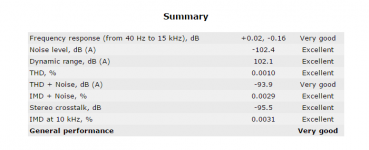
There is a bit of noise caused by the loopback condition which makes the numbers a little worse than they technically should be.
Since the performance is on the edge of what I can measure, and since from what I can tell the simulation and measured performance are in agreement, I've generally relied of the simulation as the last word.
I confirmed by measurement that the Sapphire meets the design goal of -100 dB (0.001%) THD for -3 dB output. A-weighted noise and dynamic range are better than -100 dB / 100 dB but as I said the actual figure is worse than it should be due to noise pickup in the test setup.
According to the simulation the distortion at that output level does not vary with output load impedance above 15 ohms. (it is limited always by the input voltage gain section. So I think it is reasonable to take those results as the typical operating values regardless of what headphones you are using.
Those figures quoted are for my R3X configuration, 27 dB gain. Lower gain settings should be a proportionately better still, the open loop R3 setting about 10 dB worse depending on gain setting.
Last edited:
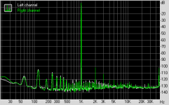
The distortion plot probably looks bad to the untrained eye but the "comb" of noise spikes is extremely low level, and related to my build and test environment not the circuit itself. (no earth connection in my house, headphone amp sits on top of my computer case, etc.) The 2-3-4th harmonics are extremely low however, and nicely match up with the simulation. So what you see looks bad but isn't important. What you don't see or notice is what you need to focus on. :-/
Attachments
Last edited:
Hey @rjm, any chance you have some measurements of this amp design? I'd like to compare it to the Objective2 - doing a custom amp build and would like to know which amp will provide the best "reference" listening experience.
LOL...comparing Richard's discrete design to an op-amp design is like comparing apples to oranges.
I've built and listened to both, personally.
In the real world, measurements and sound quality usually have little in common when it comes to your search for the best "reference" listening experience.
The Objective 2 will sound a little more "sterile" than Richard's Sapphire as a result of noticeably weaker bass.
If you don't mind the weaker bass of the Objective 2, then you may consider it the best "reference" listening experience on the planet.
")
Good luck!
I used the soundcard line out to the Sapphire input, the Sapphire output back to the soundcard line in.
This will be fine if your soundcard can exceed the Sapphire's distortion performance. That's not a given though, so check the results without the Sapphire in the loop first, then compare with the Sapphire. If no change then you are looking at the sound card performance not the Sapphire and you'll need to find a better soundcard or measurement setup.
This will be fine if your soundcard can exceed the Sapphire's distortion performance. That's not a given though, so check the results without the Sapphire in the loop first, then compare with the Sapphire. If no change then you are looking at the sound card performance not the Sapphire and you'll need to find a better soundcard or measurement setup.
You mean as a line preamplifier? Or as the output stage of a DAC?
Output stage of a DAC, unbalanced.
The output of the DAC is balanced, and commonly used op amp to unbalance. How do you suggest using Sapphire at this stage, and eliminate the use of op amp in the signal path?
So the problem there is most DAC output stages have three op amps per channel, two I/V converters, one for each phase, and then one more to filter the signals and convert to unbalanced output.
I don't know how you'd go about integrating the Sapphire into that circuit, though if you can find an output circuit that uses a CFA opamp, you should be able to substitute the Sapphire for that op amp.
I suggest consulting SNOA364c and SNOA365c.
I don't know how you'd go about integrating the Sapphire into that circuit, though if you can find an output circuit that uses a CFA opamp, you should be able to substitute the Sapphire for that op amp.
I suggest consulting SNOA364c and SNOA365c.
I am choosing cases for my Phonoclone and Saphire builds and I would appreciate any input.
I only use headphones; other than getting rid of a set of interconnects and sockets, would there be any advantage housing all the circuits in one case?
Could I disregard the output caps on the Phonoclone ?
Would there be any potential issues, such as earthing?
I only use headphones; other than getting rid of a set of interconnects and sockets, would there be any advantage housing all the circuits in one case?
Could I disregard the output caps on the Phonoclone ?
Would there be any potential issues, such as earthing?
I have no direct experience putting everything in one chassis but there is no reason it shouldn't work, per the usual caveat that the transformer should be as far away from the phono stage as possible.
It is best if you keep both the Phonoclone output cap before the volume control, and the Sapphire input cap after it. The phonoclone output cap prevents ticks and pops when changing volume, the sapphire input cap prevents the output offset voltage varying with volume.
It is best if you keep both the Phonoclone output cap before the volume control, and the Sapphire input cap after it. The phonoclone output cap prevents ticks and pops when changing volume, the sapphire input cap prevents the output offset voltage varying with volume.
- Home
- Amplifiers
- Headphone Systems
- RJM Audio Sapphire Desktop Headphone Amplifier