Thanks BamboszeK, raoultrifan, and CHIroshi! I have a Booster Board, which, according to what I read from JDS Labs on Head-Fi from their testing of agdr’s v3.1 Booster Board, shifts the limiting factor to the U1 or the gain stage op amp. That is why I am now looking to improve beyond the NJM2068DD.
Last edited:
Well...if the NJM2068 op-amp is the "limiting" factor of the O2's sound quality whether or not one is using agdr's "Booster Board", there is no shortage of other dual op-amps that you can try in place of the '2068.
The '2068 has quite low bias currents & decent SQ for a bipolar op-amp that also happens to be inexpensive.
I've tried just about every single and dual op-amp out there over the years.
Some tend to sound better if wrapped within the feedback loop of another op-amp, while others sound better without being within the feedback loop of another op-amp.
Obviously, you have to be very careful with some bipolar op-amps for U1 since you'll be feeding excessive DC straight into the 10k(VR1) volume pot.
The excessive DC will result in the 'ole "rustling leaves scenario" when turning the volume pot and reduced life for the volume pot.
I observed that when feeding the 10k pot with DC from the U1 opamp there is a scratchy sound when moving pot's knob (changing the volume). It's actually pretty loud sometimes, especially if no music is playing.
However, I don't think 2068 is limiting the SQ in any ways, instead it's limiting the max. gain, but a NE5532 or LME49720 will solve this. Although, most of us are feeding the O2 with 2V RMS, so 2068 opamp should do the job just fine.
However, I don't think 2068 is limiting the SQ in any ways, instead it's limiting the max. gain, but a NE5532 or LME49720 will solve this. Although, most of us are feeding the O2 with 2V RMS, so 2068 opamp should do the job just fine.
And 4556 is not protected in any way from it's own common mode distortions...only the psrr is good because of a super fancy power supply that would become obsolete if only you'd give a little bit of gain to njm4556...which again would make njm2068 obsolete, but we like to complicate things more often than not.Te only good idea in o2 is paralleling njm4556 if you have low impedance headphones and there's barely any good headphones below 150 ohms anyway, but this ic does not need any other ic to deliver a good sound.Use it in noninverting topology with a minimum gain of 5x for 2v input and anything up to 300 ohms will be driven really ok, but no fancy topology would be even close to the sound of a TPA6120 and i tried allmost anything around 4556 against tpa6120 in two different topologies which was claimed to have worse distortion figures than njm4556 and i don't doubt it, but i don't care either...If you want 600ohms cans then give it 10x and that is all you can get from a njm4556. The AP is not measuring a good sound, but low harmonic distortions...way lower than any headphones can deliver and again... the measurements haven't been done with real headphones attached...which makes all those thd figures claims useless.
And 4556 is not protected in any way from it's own common mode distortions...only the psrr is good because of a super fancy power supply that would become obsolete if only you'd give a little bit of gain to njm4556...which again would make njm2068 obsolete, but we like to complicate things more often than not.Te only good idea in o2 is paralleling njm4556 if you have low impedance headphones and there's barely any good headphones below 150 ohms anyway, but this ic does not need any other ic to deliver a good sound.Use it in noninverting topology with a minimum gain of 5x for 2v input and anything up to 300 ohms will be driven really ok, but no fancy topology would be even close to the sound of a TPA6120 and i tried allmost anything around 4556 against tpa6120 in two different topologies which was claimed to have worse distortion figures than njm4556 and i don't doubt it, but i don't care either...If you want 600ohms cans then give it 10x and that is all you can get from a njm4556. The AP is not measuring a good sound, but low harmonic distortions...way lower than any headphones can deliver and again... the measurements haven't been done with real headphones attached...which makes all those thd figures claims useless.
ehh... okay
well...sory if i forgot about some thousands amplifiers that can deliver at least 30w/8 ohms per channel with low noise , that can also drive any headphones in full class a mode with better specs than any specialised ic...if everything is reduced to thd figures...And i think allmost anybody can source a good vintage amplifier with headphones output taken straight from the power amplifier's output.Well it's true that i didn't try that with very low quality power amplifiers, but i can ask others to have the same "faith" in my opinions as anybody else when supported by thousands of good products launched on the market in the last 40 years...ehh... okay
I observed that when feeding the 10k pot with DC from the U1 opamp there is a scratchy sound when moving pot's knob (changing the volume). It's actually pretty loud sometimes, especially if no music is playing.
The scratchy sound you're hearing when turning the volume pot is exactly what I was referring to above as the "rustling leaves scenario" since it sounds like rustling leaves when adjusting the volume pot.
Remember, volume pots do NOT like DC being fed into them.
As for the '2068 limiting the maximum gain, that's simply NOT true.
Also, your belief that changing out the '2068 for a '5532 or LME49720 will increase the gain simply is NOT correct, either.

The gain of U1 is controlled by the ratio of R16, R22 and the values of the 3 gain switch resistors if used.
Perhaps you should learn the basics of non inverting op-amp circuits before posting stuff that simply isn't true, which could lead some other DIYers to make the same mistakes.
Remember, volume pots do NOT like DC being fed into them.
I didn't know that potentiometers are so peaky about DC...
If you have dc applied to an op-amp through a pot, the cursor is not physically in contact all the time through a linear varying resistor(plus the volume pot is usually logarithmic) which makes the dc potential to have sudden variations both at the input and output of the op-amp and these variations aren't just applied to the speaker as step response depending in speed on the input capacitance , but get in touch with the op-amp slew rate limits mostly because the offset is going to limit the maximum output which by itself leads to clipping and slew rate variations...So it's not that the Pot hates DC...
Last edited:
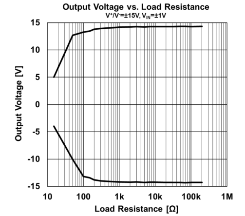
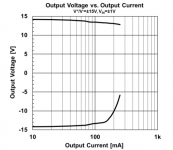
Having a look today over the new MUSES03 and just realised that could be a good candidate for output buffer against the 4652. Has a max. output current of 250mA, dissipated power of 875mA; if 2 x MUSES03 can get along when paralleled then the max. output current would be 0.5A, so a theoretical 6-7V RMS/32 ohms might be achieved...of course with some small heatsinks on top of the opamps. I would be more than happy with a clean 5V RMS/32 ohms if there's no overheating from the output buffers; that would give me about 850mW/channel, quite OK I'd say.

Now I wonder who's going to pay for 4 of such opamps and have a test.
Now I wonder who's going to pay for 4 of such opamps and have a test.
Attachments

Last edited:
Good question!Now I wonder who's going to pay for 4 of such opamps and have a test.
Any one know where objective 2 creator vanished?
This question is more than 5 years old haha - if only we knew.
Fully functional - yet not
Hello world,
I have successfully built the O2HPA from the documents and gerber files provided by nwavguy (thanks a lot for that!) and after the initial checks and tests all passed, have proceeded with using my cans to test out the amp.
Everything worked so well for the evening and the next morning - until I swapped a set of gain resistors (I've checked that, it's the correct pair at the right place with the appropriate values), things start getting really weird. The DC bias at the audio output is now at roughly +11V (AC powered) or +8V (battery only), which I managed to trace back to -ve supply rail at the power management circuit being at +2V approx. Checked the gate of n-channel MOSFET and it is exactly the same as -ve regulated supply rail / battery voltage. Thought C16 gate-source cap is shorted, swapped it for a new one, still same; maybe MOSFET was damaged, swapped that too, also no change. I have checked at a lot of places where I thought it is possible but does not seem like any traces been broken, or any possible solder whiskers/bridges present, with every intended connections alright.
For your info, right after changing the gain resistors I immediately tested it with a sacrificial IEM (which was working just fine the night before, with the same gain settings and volume) and that IEM is now fried, or at least the dynamic driver is. In the subsequent usage it normally starts OK from cold then it just suddenly gets "triggered" and the weird situation comes. Once it starts, power cycling does not help. Needs a bit of cooldown time to get it back to OK, which the whole cycle continues...
I am hoping that any kind person can help this damaged soul here. Cheers.
Sounds to me like you might have more than one problem. At the bottom of post #1 of this thread is a link which should take you to post #3775 in this thread.
Work your way through that and see where it falls down. If you suspect a problem with the rail switching (FET's and control circuit) then the FET's can be linked across from drain to source for testing. That will permanently pass the rail voltage to the audio circuitry.
Work your way through that and see where it falls down. If you suspect a problem with the rail switching (FET's and control circuit) then the FET's can be linked across from drain to source for testing. That will permanently pass the rail voltage to the audio circuitry.
- Home
- Amplifiers
- Headphone Systems
- The Objective2 (O2) Headphone Amp DIY Project