So I heard you can make these things point to point...
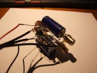
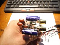
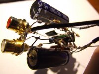
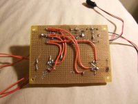
I was bored on sunday, and wanted to do something artsy, and also to check out the beautifully simple Chu Moy amplifier. The following, impossible to package, skeletal amp was the result. lol
It sounds great, but I think it may be a little too low voltage for my headphones which i think are like 65 ohms. AKG K702 Any other explanation for clipping?
Tade
Attachments
its a cmoy, do you really need the schematic? actually opamps to drive a 65r load are not unheard of, with buffer would be better of course, but any decent rail to rail I/O opa will do the job. like lme49710/20 for example
a schematic isnt really needed, but can you say what the supply voltage and opamp you are using is?
a schematic isnt really needed, but can you say what the supply voltage and opamp you are using is?
qusp, maybe you should post a schematic of what OP built since you appearently know. ") Seriously, the reason I asked for a schematic was I don't know what exactly what was built, and OP was complaining about clipping. And I will stand by my oiginal statement, not many opamps will perform optimally into a 65 ohm load even at reduced supply voltages and low drive levels.
Seriously, the reason I asked for a schematic was I don't know what exactly what was built, and OP was complaining about clipping. And I will stand by my oiginal statement, not many opamps will perform optimally into a 65 ohm load even at reduced supply voltages and low drive levels.
Mike
Seriously, the reason I asked for a schematic was I don't know what exactly what was built, and OP was complaining about clipping. And I will stand by my oiginal statement, not many opamps will perform optimally into a 65 ohm load even at reduced supply voltages and low drive levels.Mike
its a cmoy, you havent seen the cmoy schematic? seriously? a cmoy if traditional is basically nothing more than the opamp with a pot at the input and VERY basic gain network, power supply (usually 2 batteries, or 1 and a splitter formed by a capacitor bank, or resistor divider) and decoupling.
linked to Kevin Gilmore's old site and originally by Dr Chu moy, the design is so simple
reducing supply voltages for most opas, worsens the problem into a low impedance, not improves, generally it means because they dont swing as close to the rails into lowZ there becomes very little swing left. but ermm, we are talking about a cmoy, you can find an opamp that maybe performs better than whatever hes using, but basically if you add anything at all to the circuit its not a cmoy anymore. sure its not driving the headphones optimally, but its a cmoy, thats never going to happen and its not in the brief.
however i also stand by my statement, some opamps do a pretty decent job of it and 65r is actually a pretty kind load as headphones go these days, where some multidriver in ears present less than 10r at some frequencies
An externally hosted image should be here but it was not working when we last tested it.
linked to Kevin Gilmore's old site and originally by Dr Chu moy, the design is so simple
reducing supply voltages for most opas, worsens the problem into a low impedance, not improves, generally it means because they dont swing as close to the rails into lowZ there becomes very little swing left. but ermm, we are talking about a cmoy, you can find an opamp that maybe performs better than whatever hes using, but basically if you add anything at all to the circuit its not a cmoy anymore. sure its not driving the headphones optimally, but its a cmoy, thats never going to happen and its not in the brief.
however i also stand by my statement, some opamps do a pretty decent job of it and 65r is actually a pretty kind load as headphones go these days, where some multidriver in ears present less than 10r at some frequencies
Last edited:
My point was, how do you know what was actually built, there are a million variations on these things.
Tade, if you could post what you put together and what opamp was used, it would help.
By the way, I've been building opamp circuits since the uA709 days, so I do know a little bit about how to use them.
Mike
Tade, if you could post what you put together and what opamp was used, it would help.
By the way, I've been building opamp circuits since the uA709 days, so I do know a little bit about how to use them.
Mike
Last edited:
lol I need to setup a proper email adress to post replies.
That might explain the clipping... But it really sounds good. I forgot to buy 1K resistors, so i used 4.7 for a gain of only 2. But otherwise the above posted schematic is exactly right, but I build the non inverting version. Yeah, i guess there are a bunch of varieties.
Honestly, this was an afternoon boredom inspired project. I mainly just wanted to share the construction, but the help is great because I am currently bored and am gonna do the parallel suggestion. I am going to use a protoboard this time... I have some NF535N opamps that are dual packaged JFET inputs. I am going to configure them in parallel. It's a shame I haven't biwired my headphones yet because I would like to run them bridged, but I reckon I'll just build another amp.
I will repost pics when i get this built. Thanks for all the advice!
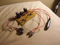
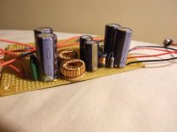
Just got done building this design:
http://i54.photobucket.com/albums/g101/D0Hbert/aph_47b.gif
I'm not proud of the back, but maybe I suck at proto boards. N535n dual opamp chips.
Check out the super audiophile approved ultra filtered 9V battery power supply. Those old computer parts needed to be used sometime.
It sounds punchy!
http://i54.photobucket.com/albums/g101/D0Hbert/aph_47b.gif
I'm not proud of the back, but maybe I suck at proto boards. N535n dual opamp chips.
Check out the super audiophile approved ultra filtered 9V battery power supply. Those old computer parts needed to be used sometime.
It sounds punchy!
Attachments
The first one you made was clipping probably. I'm not sure of the opamp you were using for the ptp one but they usually don't have the output required for lower Z applications. Assuming you are using 25v components, try +9/-9v and not +4.5/-4.5. That should help a lot. I recently ran into that problem myself. A Cmoy like that one really benefits from a rail to rail opamp and true ground.
The new one you built looks better already.
The new one you built looks better already.
Uhgg.. I just noticed that you used the old Apheared's 47 amp schematic. While it is a decent idea, the resistors values used for the current matching are abysmal. Please tell me you did not use 47-Ohm as that schematic indicates. That is sure to make your output resistance very high. You could probably get away with 2-Ohm or even 1-Ohm.
I'm pretty sure I remember they guy saying that he used that value because he had no smaller values left at the time. It is important that the current matching resistors are at least 1%. I would hand match those to 0.1% even. While I understand the propensity to "use what you got", it's probably not the best idea to draw the schematic that way.
I'm pretty sure I remember they guy saying that he used that value because he had no smaller values left at the time. It is important that the current matching resistors are at least 1%. I would hand match those to 0.1% even. While I understand the propensity to "use what you got", it's probably not the best idea to draw the schematic that way.
Last edited:
Rembrant, for opamps with small current drive capabilities, 47 ohms or even a litte higher is appropriate, the smaller values you suggest would overload the outputs and increase distortion. And because they are inside the feedback loop, the output resistance is low, the only pentalty is a slightly lower output voltage. I agree that using two 9 volt batteries is much better.
Mike
Mike
Could the C-Moy be used to feed some PNP/ NPN' to give an increase in the current output of the amp ? If so could you then go further and end up with a workable amp in, say, the 100watt range ?
I have built one of these C-Moy's myself using the same parts and varying the op-amps and adding a better power supply. Personally I found it to be O.K soundwise, maybe a little closed-in sounwise, but apart from that, for what is a minimal amount of parts and effort - pretty good. Could I build further and extend the design out though ?
Thanks
Gareth
Rembrant, for opamps with small current drive capabilities, 47 ohms or even a litte higher is appropriate, the smaller values you suggest would overload the outputs and increase distortion. And because they are inside the feedback loop, the output resistance is low, the only pentalty is a slightly lower output voltage. I agree that using two 9 volt batteries is much better.
Mike
Ok. I can't find any NF535n Opamp in searches so I can't look at the data sheet. The idea of parallel opamps is to increase current to an acceptable level. If the two of them parallel still doesn't have the current available to drive his phones, then those 47 Ohm resistors are just a crutch anyway and the phones are not still not being driven properly. Then what is the point of building it?
Doing the math, I get around 9-Ohm output impedance with the 47-Ohm resistors. If you add the battery impedance it is slightly more. With 2-Ohm resistors there, it drops to around .9-ohm plus battery. The feedback loop isn't some magical fairy that removes output impedance.
Anyone know what Opamp he is talking about so we can at least look at the data sheet? The OPA2132, like the schematic indicates, should have enough current in parallel for 32-Ohm phones. I have no idea what a NF535n is. Neither does Google for that matter.
http://www.eecs.umich.edu/~aey/eecs210/lectures/amp.pdf
Obviously, I don't have the tade's amp here to make measurement's, so the value is a guesstimate at best. Note, the qualifier used was around.
I can't be the only person around here that remembers the actual thread at headwize where this exact topic was discussed and it was decided at the time that the 47-Ohm resistors were on the large side. That was quickly followed by the author's admission that those were the resistors that he had on hand and he did try lower values at a later date and they didn't sound as good to him as 47-Ohm.
I tried to find the original thread at headwize. I got about this far...HeadWize - Project: Apheared's Project Scrapbook by Michael Shelton If you try to click the forum links near the bottom they 404.. I didn't try to backtrack through the entire DIY section to see if I could find that thread. My memory isn't the greatest. Perhaps this is a fabrication of my imagination. I'm pretty sure it isn't though. This time.
Last edited:
- Status
- This old topic is closed. If you want to reopen this topic, contact a moderator using the "Report Post" button.
- Home
- Amplifiers
- Headphone Systems
- Tade's new CMoy amplifier