i recently built an actively-loaded (CCS) szekeres headphone amp to drive my hd595 50-ohm headphones, to much success, documented here.
so, since i liked the sound of the ac-coupled szekeres, i decided i'd take the design a bit further:
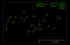
- replace the lm317 ccs with an irf610, buffered with an npn bjt.
- increase the quiescent current draw (again) to 550mA.
- add a low-pass filter to the input to smoothly roll off HF.
- increase output capacitor (again) from 4700uF to 8000uF.
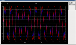
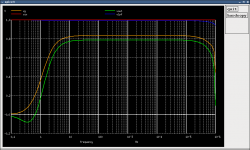
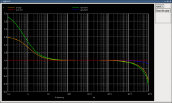
while none of these modifications are completely original, i think they're all worth adding. i've attached the simulation results from spice.
the irf610 dissipates around 6W and the irf640 around 2W, if my calculations are correct, and spice predicts 0.018% THD for a 1Vpp, 1kHz input. (lower than that simulated for resistor-loaded and lm317-loaded szekeres) frequency response seems adequate.
of course, i'm looking for feedback from anyone who has comments or corrections to the design. your insights are welcome, as i'll be the first to posit that i'm not the most experienced circuit designer. so, what do you think?")
~ brad.
so, since i liked the sound of the ac-coupled szekeres, i decided i'd take the design a bit further:
- replace the lm317 ccs with an irf610, buffered with an npn bjt.
- increase the quiescent current draw (again) to 550mA.
- add a low-pass filter to the input to smoothly roll off HF.
- increase output capacitor (again) from 4700uF to 8000uF.
while none of these modifications are completely original, i think they're all worth adding. i've attached the simulation results from spice.
the irf610 dissipates around 6W and the irf640 around 2W, if my calculations are correct, and spice predicts 0.018% THD for a 1Vpp, 1kHz input. (lower than that simulated for resistor-loaded and lm317-loaded szekeres) frequency response seems adequate.
of course, i'm looking for feedback from anyone who has comments or corrections to the design. your insights are welcome, as i'll be the first to posit that i'm not the most experienced circuit designer. so, what do you think?
~ brad.
Attachments
It looks good to me, the only thing I question is why the output cap is so large (8000uF driving a 50R load gives a cut off frequency of about 0.4Hz). The extra inductance which comes with such a large cap, while small, does have a detrimental effect. I do note that you've bypassed the cap but this is a bandaid for a problem which can be mitigated by using a smaller cap, say 1000uF and still have an excellent low frequency cutoff of around 3Hz. Worth noting also is that the input cap and the bias resistors create a lowpass filter of around 1.4Hz anyway.
A possible suggestion also, while I've not done the math to figure out where your DC bias point is myself, from your description of the power dissipation in the two FETs I'd expect your DC bias voltage to be somewhere around 4V. This will allow an asymmetric maximum voltage swing. While the 3V or so of negative swing is plenty for most headphones, why not move your output bias up to ~7V to give yourself more headroom? An additional benefit of this is the more balanced power dissipation which should make heat sinking easier.
I hope this is of some use to you.
Mike.
... the only thing I question is why the output cap is so large ... The extra inductance which comes with such a large cap, while small, does have a detrimental effect.
hmm, an interesting observation on the cap inductance at that size... never considered that. i suppose that inductance due to parallelling multiple (5-8x1000uF, or 2-3x3300uF)elna silmic ii's together would only aggravate the problem, right?
... this is a bandaid for a problem which can be mitigated by using a smaller cap, say 1000uF and still have an excellent low frequency cutoff of around 3Hz.
i used a 4700uF panasonic FC in my first szekeres, and it seems to be ok. what would parasitic inductance 'sound' like if it did exist?
Worth noting also is that the input cap and the bias resistors create a lowpass filter of around 1.4Hz anyway.
but a 4.7uF input cap and 100k bias shunt resistor yield a -3dB corner of 0.4Hz.
... I'd expect your DC bias voltage to be somewhere around 4V. ...
makes sense. ok, so i changed the bias series resistor to 25k, the ccs collector resistor to 1.5k, and the rail voltage to 18V and the simulator gives me a gate bias of 14.4V and a source bias of 7.2V. thanks!
thanks for the feedback!
~ brad.
Using multiple output caps in parallel has the effect of reducing the ESL which actually helps you. The effect of parasitic inductance can be two fold, the most obvious is that it will create a lowpass filter attenuating some of your higher frequencies. Usually this occures well above the audiable range, though that never stopped audiophiles from worrying about things. The second and possibly more damaging possibility is oscillation in extreme cases. This is expecially a problem when you parallel caps. A parallel LC circuit has a minimum impedance at its resonant frequency and if you have any noise close to this frequency you can end up with oscillation. Most of the time you can ignore this and you'll never have a problem, but it's something to keep in mind, especially if you start having strrange problems.
For your input cap, you need to include the effect of R4 which, for AC signals, is effectively in parallel with R3. This is how I came to the 1.4Hz figure.
Always happy to help.
Mike.
For your input cap, you need to include the effect of R4 which, for AC signals, is effectively in parallel with R3. This is how I came to the 1.4Hz figure.
Always happy to help.
Mike.
ah, ok the 1.4Hz makes sense now too. my plan is to power this using a salas shunt regulator, so noise shouldn't be a problem. depending on how the rest of my simulations go, i'll be parallelling 5-8 1000uF elna silmic ii 'lytics for each channel, so i'll check out the specs on those caps.
thanks again for all the input!
~ brad.
thanks again for all the input!
~ brad.
perhaps an even better idea than simply springing for higher quality components and better bias points: has anyone tried this circuit with a dc servo? if so, what difference in sound did you observe?
i want to keep the amp musical and not venture into the analytical...
thanks,
~ brad.
i want to keep the amp musical and not venture into the analytical...
thanks,
~ brad.
A lot of amps use DC servos. Some people on this forum despise servos! So it's application is very critical and if not done right it degrades the sound.
I haven't seen what needs to be done as points 1,2,3 etc. to make sure it is inaudable. It must be to do with the right time constants of the dc filter and the loading effects of the filter circuit.
Search for 'dc servo' on this forum and you might come across several experiments and opinions. Remember that the FINAL opinion is always yours and it CAN be different from what others think. So DO experiment ! AND please report your view point even if it differs from 99% of the others !
Last edited:
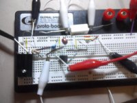
as a sanity check, i threw together a basic breadboarded circuit. one irf640 with 10 ohm source resistor to ground. B+ was 13.8V. i used an ad823 with integrating R=470k and C=0.47uF (tau=0.22s) to set the gate bias through a 100k resistor. similar to the attached image found on the szekeres amp addendum page at headwize, but without the 2.2k resistors and extra rc filter before the integrator.
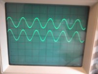
works as it should. the scope shows that the source voltage tracks the voltage set using the resistive divider and the fet is biased well into class a.
using a 470uF (small, yes) lytic on the output, a listening test confirmed the amp works in such a configuration. (yeah, kind of defeats the point of the servo, but i don't have a split psu.) it sounded about as good as a resistor-loaded, overbiased, high input capacitance szekeres can.
~ brad.
Attachments
wait a second...
actually, now that i (finally) got around to measuring, there's almost a 1V difference (source 8.93V, resistor divider 9.73V) between the voltage divider and the source, and i'm not sure why... any suggestions from more experienced folk?
[edit: could it be the fact that i'm running both the amp and the servo off the same rail voltages? though the ad823 is a rail-to-rail opamp...]
~ brad.
works as it should.
actually, now that i (finally) got around to measuring, there's almost a 1V difference (source 8.93V, resistor divider 9.73V) between the voltage divider and the source, and i'm not sure why... any suggestions from more experienced folk?
[edit: could it be the fact that i'm running both the amp and the servo off the same rail voltages? though the ad823 is a rail-to-rail opamp...]
~ brad.
Last edited:
Yay!
it works!
i changed my resistor divider from 30k/100k to 30k/30k and the dc offset went away, since the opamp could provide enough voltage for the new bias point. currently i'm listening to the amp in mono form, and i'm using the other half of the AD823 to buffer the "ground" point between the dividing resistors, meaning no output coupling cap on a single supply. the sound is quite good for something i threw together from junkbox components.
i'll have a schematic of what i've hacked together up soon.
~ brad.
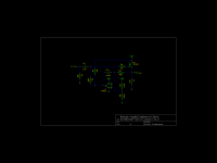
here's what is working...
ok, attached is the circuit which i've breadboarded. it's working with no dc offset between the resistor divider and the source. i have listened two ways:
i'm very interested in testing this further. i'll post my results here. please give me your suggestions or comments, if you have any.
~ brad.
ok, attached is the circuit which i've breadboarded. it's working with no dc offset between the resistor divider and the source. i have listened two ways:
- 470uF output electrolytic: panasonic FC, regular ground is used
- other half of ad823 buffers resistor divider groundpoint, no output cap
i'm very interested in testing this further. i'll post my results here. please give me your suggestions or comments, if you have any.
~ brad.
Attachments
it seems after working further into the servoed szekeres, i have to say i still prefer the sound of my first build. this is probably more for religious reasons, as i've realized that adding an opamp into the audio chain is leaving the innate simplicity of the szekeres. for that amount of complexity, it'd probably be more worth my while to think about an M^3. and honestly, if any mod to the stock szekeres is going to raise performance, it's the replacement of the source resistor with a fet-ccs, not the removal of the output cap. (IMHO, correct me if i've made a grievous error here.)
so i've decided to stick with my original design, more or less. i'll post the new schematic here soon.
~ brad.
so i've decided to stick with my original design, more or less. i'll post the new schematic here soon.
~ brad.
listening both my first amp and the servoed design with my sennheisers, it seems to me that the first has a less reserved sound, possibly due to the act of buffering the ground through an opamp in the servoed version. just my attempt at an explanation.
another interesting tidbit, not related to the comparison between topologies, is the fact that the szekeres reveals sonic differences in the source it's driven by. for example, my iriver (wolfson wm8731l) seems to have a bit less detailed sound than my pc line out (???). for instance, beat frequencies between notes played on a synthesizer were only audible using the szekeres with my pc.
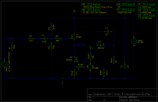
i've attached what i feel to be a fairly complete description of my next headphone "amp" project... i've decided to spring for salas shunt regulators as an upgrade to the previously used lm350k series reg, and i've separated the power rails and grounds for each channel to minimize crosstalk without venturing into true dual mono territory.
~ brad.
another interesting tidbit, not related to the comparison between topologies, is the fact that the szekeres reveals sonic differences in the source it's driven by. for example, my iriver (wolfson wm8731l) seems to have a bit less detailed sound than my pc line out (???). for instance, beat frequencies between notes played on a synthesizer were only audible using the szekeres with my pc.
i've attached what i feel to be a fairly complete description of my next headphone "amp" project... i've decided to spring for salas shunt regulators as an upgrade to the previously used lm350k series reg, and i've separated the power rails and grounds for each channel to minimize crosstalk without venturing into true dual mono territory.
~ brad.
Attachments
then again, ...
ok, working with the simulations i found discomforting hf instability with my newest design. the frequency response would peak at 1.8mhz, phase response was no better, and since i didn't like the input low-pass filter to begin with, i decided to fix it.
taking note of the base resistor in the ccs of the zen-like (in topology, not simplicity) headphone amplifier, i upped mine to 1k and moved the ccs capacitor to a safer and more useful location. since this fixed the issue at hf, i was able to remove the input lpf.
i've attached the newest revision to this post.
~ brad.
Attachments
Keep in mind that if you're using the 100uF cap to fix your HF oscillation issues, that in reality a 100uF cap, which is likely to be an electrolytic will act as an inductor at anywhere near 1.8MHz. You'll need a parallel ceramic or film cap (100nF should do) just to get those high frequencies.
It's been interesting watching your design evolve. Keep it up.
Mike.
It's been interesting watching your design evolve. Keep it up.
Mike.
Keep in mind that if you're using the 100uF cap to fix your HF oscillation issues, that in reality a 100uF cap, which is likely to be an electrolytic will act as an inductor at anywhere near 1.8MHz. You'll need a parallel ceramic or film cap (100nF should do) just to get those high frequencies.
actually the modification of the base resistors in the ccs fixed the hf issue, but bypassing the 100uF cap with a film cap can't hurt.
thanks.It's been interesting watching your design evolve. Keep it up.
thanks.
i'm very glad my postings are of use.~ brad.
thanks.
well, i'm looking at heatsinks currently... my last design had the FET and CCS mounted via mica spacers to the case, which was barely large enough to act as a decent heat sink. it was a bit more artful than functional...
so my plan here is to use natural convection through the case to cool the FETs, which will be mounted on actual commercially available sinks. it seems that the wakefield 657-15abp should do the job, with R_theta=6.3 K/W under natual airflow. they seem to be capable of handling the 6.6W of dissipation that M101 and M201 will produce, right?
~ brad.
- Status
- This old topic is closed. If you want to reopen this topic, contact a moderator using the "Report Post" button.
- Home
- Amplifiers
- Headphone Systems
- my take on the szekeres