Using a resistor divider is a better method. The use of a dedicated rail splitter (TLE2426) is the best way to prevent differences in rail voltages.
There's a lot of information (with schematics) on this subject here:
Virtual Ground Circuits
There's a lot of information (with schematics) on this subject here:
Virtual Ground Circuits
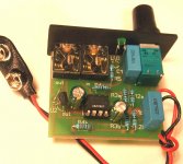
Thanks for the explanation, although I'm a bit confused by it! Here's another photo (with the LED lead pulled out of the way, so you can see what's happening with the leads to the capacitors):
You're telling me to connect a resistor in parallel across the capacitors, and to alter the connections to the switch, presumably so it looks something more like the supply to this standard CMOY circuit?
An externally hosted image should be here but it was not working when we last tested it.
You're telling me to connect a resistor in parallel across the capacitors, and to alter the connections to the switch, presumably so it looks something more like the supply to this standard CMOY circuit?
An externally hosted image should be here but it was not working when we last tested it.
Using a resistor divider is a better method. The use of a dedicated rail splitter (TLE2426) is the best way to prevent differences in rail voltages.
There's a lot of information (with schematics) on this subject here:
Virtual Ground Circuits
Thanks for the link, Beftus, and from what I've read there the sound will be distorted long before the voltage drops sufficiently to cause a DC offset problem. That said, I do fall asleep sometimes using my headphones...
Yep - the way I described the switch is different, but if you work through my post with those diagrams for reference, you'll figure it out.
I was suggesting that the least-effort method was to switch the connection between the batteries, whereas that version switches between the battery and the board - which is the way I'd do it if I was building from scratch.
I was suggesting that the least-effort method was to switch the connection between the batteries, whereas that version switches between the battery and the board - which is the way I'd do it if I was building from scratch.
Incidentally, that board design is utterly horrible - take a quick look over Tangent's tutorial, you could do a better job on protoboard.
How to Build the CMoy Pocket Amplifier
How to Build the CMoy Pocket Amplifier
BTW, the use of 0.1µF input caps in a bog standard CMoy is not recommended by Tangent. A 1.0µF input cap is a better choice. Read this: Input Capacitors for Headphone Amps
I see TheSeekerr good describe practical way to fix this amp.
Johnny Blue, here is my step by step tutorial:
1. Remove two wires from switch to board completely
2. Desolder from switch two wires, coming from both battery, connect both wires together and isolate
3. Desolder from board one wire, coming from battery + terminal (red)
4. Solder in this place spare red wire
5. Solder switch between this wire and desoldered battery + wire
6. Solder two 4.7K - 10k resistors paralell to el caps. You can use any resistance in this range, important is - both must be matched at least 1%. This determine both voltages equal and low DC offset.
Now measure voltages between ground and +, ground and -, both must be equal.
Now measure DC offset in both channels, if it is good, you are ready to connect phones.
However this board is very strange") , both el. caps are in surprising right place, close to chip, near the chip's power pins (almost like in by boards). This increase sound quality, however not many CMoys builder use this technique, common in Gainclone.
, both el. caps are in surprising right place, close to chip, near the chip's power pins (almost like in by boards). This increase sound quality, however not many CMoys builder use this technique, common in Gainclone.
To utilize this better, solder caps deeper in board, with as short as possible legs.
Maybe, if your enclosure allow it, you can solder both rail splitter resistor on boards other side, right to caps pads.
Johnny Blue, here is my step by step tutorial:
1. Remove two wires from switch to board completely
2. Desolder from switch two wires, coming from both battery, connect both wires together and isolate
3. Desolder from board one wire, coming from battery + terminal (red)
4. Solder in this place spare red wire
5. Solder switch between this wire and desoldered battery + wire
6. Solder two 4.7K - 10k resistors paralell to el caps. You can use any resistance in this range, important is - both must be matched at least 1%. This determine both voltages equal and low DC offset.
Now measure voltages between ground and +, ground and -, both must be equal.
Now measure DC offset in both channels, if it is good, you are ready to connect phones.
However this board is very strange
, both el. caps are in surprising right place, close to chip, near the chip's power pins (almost like in by boards). This increase sound quality, however not many CMoys builder use this technique, common in Gainclone.To utilize this better, solder caps deeper in board, with as short as possible legs.
Maybe, if your enclosure allow it, you can solder both rail splitter resistor on boards other side, right to caps pads.
Beftus,
there is two ways to increase low frequency, if input caps are used:
1. Increase cap from 0.1 to 1.0-2.0 mf
1. increase input to ground resistors from 100K to 1M
I use 1Mohm input resistor and 0.22mf, good quality polypropylene with great success.
B.T.W. If someone is interested, I can offer CMoy PCBs and kits with high quality parts. Boards size is 4 x 5 cm, designed for Hammond 1593PBK enclosure.
Attachments
This would also necessitate the use of a 100K volume pot instead of a 10K pot.increase input to ground resistors from 100K to 1M
This would also necessitate the use of a 100K volume pot instead of a 10K pot.
I use lile different schematic - 10K pot right after input jack, then 0.22uF cap, then chips + input pin with 1M to ground.
Saying that the electrolytic caps are in the best possible place is missing the point - they shouldn't be electrolytics in the first place, the caps there should be 0.1uF ceramics, with some 1-6uF films nearby, and the bigger electrolytic caps typically further away to help make the board layout tidy.
Short version: Decoupling caps should be small.
Short version: Decoupling caps should be small.
Ceramics are not good for audio at all, for decoupling better is film caps - polypropylene of at least polyester.
Years ago CarlosFM bring in this forum idea about decoupling preamp chips with low ESR 47uf-100uf as close as possible to power pins, paraleled with 0.1uf film cap, better on other boards side, direct on chips power pin.
Many, including me, notice improvement in sound quality this way.
For example in Gainclones common practice is solder 1000uf-2200uf close to chip power pins, in p2p version - direct to chip pins, shunted with 0.1 film.
Think about CMoy as miniaturized Gainclone.
I'm not saying that having electrolytics near the power pins is bad - I'm saying that having small caps near the power pins is better - so much better that that electrolytics can be further away.
As for your assertion that ceramics are no good for audio, I disagree - for power supply decoupling, their properties are suitable. Film caps are indeed more linear, but they're also more expensive.
As for your assertion that ceramics are no good for audio, I disagree - for power supply decoupling, their properties are suitable. Film caps are indeed more linear, but they're also more expensive.
I see TheSeekerr good describe practical way to fix this amp.
Johnny Blue, here is my step by step tutorial:
1. Remove two wires from switch to board completely
2. Desolder from switch two wires, coming from both battery, connect both wires together and isolate
3. Desolder from board one wire, coming from battery + terminal (red)
4. Solder in this place spare red wire
5. Solder switch between this wire and desoldered battery + wire
6. Solder two 4.7K - 10k resistors paralell to el caps. You can use any resistance in this range, important is - both must be matched at least 1%. This determine both voltages equal and low DC offset.
Now measure voltages between ground and +, ground and -, both must be equal.
Now measure DC offset in both channels, if it is good, you are ready to connect phones.
However this board is very strange
To utilize this better, solder caps deeper in board, with as short as possible legs.
Maybe, if your enclosure allow it, you can solder both rail splitter resistor on boards other side, right to caps pads.
Thanks for this, Zigis: with your step-by-step tutorial, I believe I can make the necessary changes. I assume this "measure voltages between ground and +, ground and -" means between red and black wires? (See, I'm very new to this!) And how do I "measure DC offset in both channels"? (I do have a Digital Multi-Meter, but don't know where to measure!)
The reason I left the longs legs on the input caps was so I could bend them over to allow the kit to fit into a tin (which is what the eBay seller of the original kit shows in some listings: look at his first picture).
The subsequent discussion about the value and types of cap in the preceding posts are way over my head, but I hope to understand them at some point in the future!
As for your assertion that ceramics are no good for audio, I disagree - for power supply decoupling, their properties are suitable. Film caps are indeed more linear, but they're also more expensive.
They do have good properties/specs, but they sound much worse than film caps. I think this is what Zigis is saying too.
In the signal path? Maybe - although I can think of at least one popular DIY headphone amp which does have a ceramic in the signal path and sounds brilliant.
As a decoupling cap? I don't believe so - in my opinion, two power supplies having the same voltage, sufficient current capacity, similar levels of ripple and similar noise spectra will sound the same - but then, I'm not a tweaker, not a golden ear, not a true believer - I'm an adherent to the scientific method who aspires to being an engineer.
OK, this goes a bit ranty here - please note that this is NOT an attack on Mike, or Zigis, or anyone else. It's just an experiment - one I think is worth attempting.
Go on, build two identical amplifiers. Match them as closely as you can - but swap the ceramics out for film caps. Drive them from the same source, and use a switched headphone jack to listen through the same headphones. Now employ an assistant to help you conduct an ABX test - it's only single blinded, but it'll do.
You know what, I bet you can't hear the difference - that over 100 tests, you'll do no better than someone who's guessing.
What's my point? That anecdote is not evidence.
I'm not saying that having electrolytics near the power pins is bad - I'm saying that having small caps near the power pins is better - so much better that that electrolytics can be further away.
As for your assertion that ceramics are no good for audio, I disagree - for power supply decoupling, their properties are suitable. Film caps are indeed more linear, but they're also more expensive.
Yes, both - small film cap and medium el cap close to pins is good. We DIYers or even small amount producer (contrary to factory robots) can realize both, as I say before - design PCB with decoupling el caps close to power pins, after all components are soldered, solder 0.1uf film caps on PCB's left side, direct on chip pins. Closest is not possible
This brilliant idea is from Carlos too.
To be honest, I am not making decoupling caps A/B tests, you described, many say - film caps sound better, I simply put here cheap polyester and focus on other sound improvement questions.
I assume tVhis "measure voltages between ground and +, ground and -" means between red and black wires? (See, I'm very new to this!) And how do I "measure DC offset in both channels"? (I do have a Digital Multi-Meter, but don't know where to measure!)
Ground is where both new resistors are connected together. I see your headphone socket is with metal ring, there is ground connected too.
Measure voltage between this ring and red wire, than between ring (ground) and black wire. Both must be equal, about 9V with 2 new battery, just in reverse polarity.
Then turn your DMM to mV and measure DC offset between output connector's central connector or ring (ground) to right output and to left output, if both are less than 20mV, amp is good working and safe.
Does anyone know a circuit to implement bass boost into a Cmoy?
In general, this is RC filter in series with feedback resistor.
You can see in amb's M3 schematic:
The M³ Stereo Headphone Amplifier
this is 3 channel amp with buffered output, see bass boost part only, there is bass boost calculator too.
- Status
- This old topic is closed. If you want to reopen this topic, contact a moderator using the "Report Post" button.
- Home
- Amplifiers
- Headphone Systems
- CMOY shootout!