Ground is where both new resistors are connected together. I see your headphone socket is with metal ring, there is ground connected too.
Measure voltage between this ring and red wire, than between ring (ground) and black wire. Both must be equal, about 9V with 2 new battery, just in reverse polarity.
Then turn your DMM to mV and measure DC offset between output connector's central connector or ring (ground) to right output and to left output, if both are less than 20mV, amp is good working and safe.
Thank you, Zigis, for spelling this out for me (I think I should avoid DIY fora and stick to the hi-fi ones!).
I think I should avoid DIY fora and stick to the hi-fi ones!
Why would you do that? Stick around, read things that interest you and try to understand and learn new stuff. DIY is fun and highly rewarding when stuff you make actually works!
Why would you do that? Stick around, read things that interest you and try to understand and learn new stuff. DIY is fun and highly rewarding when stuff you make actually works!
Yes, of course I will! I only wrote that to cover my embarrassment at my ignorance of electronics. I wish I'd paid greater attention in Physics, but all I can remember is V=IR, I and R are measured in series, V in parallel (and under load). That's it!

That pretty much applied to me too as I started to build my own LM3886 mono blocks. I have made a class A amp (mini Aleph) and a tube preamp since then. Still under construction are a buffer preamp (First Watt B1), a CMoy headphone amp and another class A amp (First Watt F5).all I can remember is V=IR
Awe shoot, I was looking for the simple old ohm chart, V on top over a line, I x R underneath.
To find value of the [v, i, or r] one you don't have put a thumb over the chart on that 'thing's value you need, insert and calculate the other two values you do have to get it.
But then I found this:
Ohm's Law
A bit more complicated but better than coles law.
To find value of the [v, i, or r] one you don't have put a thumb over the chart on that 'thing's value you need, insert and calculate the other two values you do have to get it.
But then I found this:
Ohm's Law
A bit more complicated but better than coles law.
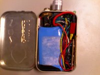
Here's mine.
Ordered the PCB from Walking Wolf on E-bay, have since had to partially rebuild it (using better components) after accidentally reversing the polarity from the battery... oops. Using a OPA2107. Battery is 11.1V 1200mAh Lithium Polymer stolen from one of my model airplanes. It's a tight fit, but it provides over 200 hours of playing time between charges.
Ordered the PCB from Walking Wolf on E-bay, have since had to partially rebuild it (using better components) after accidentally reversing the polarity from the battery... oops. Using a OPA2107. Battery is 11.1V 1200mAh Lithium Polymer stolen from one of my model airplanes. It's a tight fit, but it provides over 200 hours of playing time between charges.
Attachments
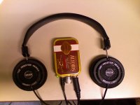
Here's mine. Got the Alps pot today. Popped in an OPA2134. Works first time. Sounds great. Popped in an AD8066, souds great too. Plays plenty loud on my PX-100's. Bass boost is a nice feature, some music really benefits from it. Not all music needs it though. I tamed the bass boost feature a bit, I'm glad I did, mine is ~6 dB. Default bass boost is a whopping ~9 dB.
Attachments
Hi mate
Ive seen these on eBay. Let me know how it sounds.
Howdy matey,
6 weeks later and it still hasn't arrived, the seller is sending me another so I'll let you know as soon as I can.
Chow.
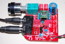
I just boxed up the red cMoyBB in a transparent blue Hammond enclosure. I also almost finished my green cMoyBB today. Yup I've made another one...
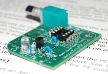
The green one is DC coupled and as of writing is still missing its bass boost pot. I also used miniature 1/8W resistors on this one. Gain of this green one is 6.5. I'm gonna let it play for a couple of hours to burn in. Picture shows it as it was in progress.
The green one is DC coupled and as of writing is still missing its bass boost pot. I also used miniature 1/8W resistors on this one. Gain of this green one is 6.5. I'm gonna let it play for a couple of hours to burn in. Picture shows it as it was in progress.
Attachments
I made my Cmoy P2P, I still remember the moment it came to life. I heard things (sounds) in songs I did not know existed. It sounded like I added 12" woofers to my Sony MDRs
I used a Mitsubishi 5218A. I have nothing to compare it to, but it sounds great. I think it has around 0.0015 THD and runs of very low voltage. It makes things sound better even at moderate listening levels. I have left it turned on (no audio) for over a week and was still able to use it for quite some time after that.
I'm not sure what I tore the chip out of, but it's a fairly common op-amp cause I have 3 or 4 of them kicking around.
One day I would like to build the Cmoy right into a pair of headphones. I think that would be handy. I built it into a belt pack and don't use it nearly enough, mainly because I am a carpenter who wears a tool belt all day and have enough stuff to worry about hanging off me.
First timer here. Just finished my first Cmoy. A built a Banzai 2.0 and sounds pretty good for 20 bucks.
I already have the parts for the JDS Audio Cmoy. My only problem is I need a better hole puncher for the Altoids can.
With the Beyers DT880 sound is a little thin but still OK.
All in all I am really excited at good results with my first ever DIY!
I already have the parts for the JDS Audio Cmoy. My only problem is I need a better hole puncher for the Altoids can.
With the Beyers DT880 sound is a little thin but still OK.
All in all I am really excited at good results with my first ever DIY!
I see TheSeekerr good describe practical way to fix this amp.
Johnny Blue, here is my step by step tutorial:
1. Remove two wires from switch to board completely
2. Desolder from switch two wires, coming from both battery, connect both wires together and isolate
3. Desolder from board one wire, coming from battery + terminal (red)
4. Solder in this place spare red wire
5. Solder switch between this wire and desoldered battery + wire
6. Solder two 4.7K - 10k resistors paralell to el caps. You can use any resistance in this range, important is - both must be matched at least 1%. This determine both voltages equal and low DC offset.
Now measure voltages between ground and +, ground and -, both must be equal.
Now measure DC offset in both channels, if it is good, you are ready to connect phones.
However this board is very strange
To utilize this better, solder caps deeper in board, with as short as possible legs.
Maybe, if your enclosure allow it, you can solder both rail splitter resistor on boards other side, right to caps pads.
Zigis, can you please look at my modified circuit in the attachment and tell me if it is correct?
I have followed your instructions as above (I think!).
Attachments
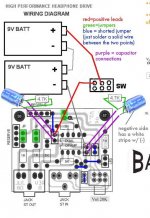
Hi taliesyn, yes circuit look correct.
Before connecting phones, measure voltage between ground and both chip power pins (4 and 8), both must be equal, with opposite polarity. Then measure DC offset on output.
Goo luck!
I will do that. Thanks
How did you go with the mods to the circuit. I have just purchased the same kit (waiting for it to arrive) and will impliment the same changes if it all went well.I will do that. Thanks
Thanks Tom
I have a problem on the bass boost that I have added,
this is the one I found here
and the schematic is this one:
 (for each channel)
and i followed that scheme and make my own:
Left

Right

now the problem is, i dont know why it doesnt make any changes when i turn it on/off.
questions are:
1. is the original schematic (1st image) correct for bass boost?
2. are my own schemes (2nd & 3rd image) correct?
3. did i burn or damaged my "bass boost" resistor and cap?
4. it is still working perfectly right now, even with the bass boost switch is on/off, its just that it doesnt make any changes when i select it. if it was damaged (#3), does the amp still work?
5. as you can see, the values in the original bass boost circuit, especially the cap is different from the one i did? I know the fact that the higher its values, the lesser it cuts off the low frequency. but at least i can hear difference because of it, am i correct?
thanks
this is the one I found here
and the schematic is this one:
and i followed that scheme and make my own:
Left
Right
now the problem is, i dont know why it doesnt make any changes when i turn it on/off.
questions are:
1. is the original schematic (1st image) correct for bass boost?
2. are my own schemes (2nd & 3rd image) correct?
3. did i burn or damaged my "bass boost" resistor and cap?
4. it is still working perfectly right now, even with the bass boost switch is on/off, its just that it doesnt make any changes when i select it. if it was damaged (#3), does the amp still work?
5. as you can see, the values in the original bass boost circuit, especially the cap is different from the one i did? I know the fact that the higher its values, the lesser it cuts off the low frequency. but at least i can hear difference because of it, am i correct?
thanks
Hi All,
I would like to give-back to the this website/forum because you guys helped a lot in my 1st project.
My story is...
Few weeks back i purchased exactly what Johnny Blue have. Banzai CMOY with 2x 9V supply. It's only a kit that has everything for the build except for the batteries and casing. Assembled it for few hours, found a cheap plastic that enclosed everything well. It was a success! my m50 sounded full and more exciting than unamped. I was happy with my project.
After several hours of usage, approx 10-12 hrs. There was so much distortion, tried to turn off CMOY and after turning ON, for few seconds it was distortion free, but again distortion occurs. Suspecting a low battery problem, I completely turn off my CMOY.
The next day I check the Voltage level of both batteries, both have around 5V each. It was sad thinking that my CMOY would only run for around 10hrs. Then I ended up in this site, discussing design problem with Banzai Cmoy.
I followed exactly recommendations and step by step guide of Zigis & TheSeekerr. After the modification, I was able to use set of batteries that already has 10-12hrs of use. That early distortion problem could be fault of the design. But thanks to you guys, I think my CMOY is now better.
I also added a DC socket that would give an option to save my batteries for Home and Office use.
Again thanks to all,
An externally hosted image should be here but it was not working when we last tested it.
How did you go with the mods to the circuit. I have just purchased the same kit (waiting for it to arrive) and will impliment the same changes if it all went well.
Thanks Tom
Changed the amp and forgot about this thread entirely!
Modifications were absolutely fine. Perfect in fact. DC offsets fine and also correct voltages supplied to the op amp.
Thanks to Zigis for looking over the modified diagram
- Status
- This old topic is closed. If you want to reopen this topic, contact a moderator using the "Report Post" button.
- Home
- Amplifiers
- Headphone Systems
- CMOY shootout!