Hi Andrew,
I'll put another blank line in the wiki. In the future, you can just copy the line, paste twice then fill in your info using the top line.
I haven't looked into pricing since the beginning. I figure we should wait for the design to stabilize. The usual breaks are around 50 pieces apart, though.
Bob
I'll put another blank line in the wiki. In the future, you can just copy the line, paste twice then fill in your info using the top line.
I haven't looked into pricing since the beginning. I figure we should wait for the design to stabilize. The usual breaks are around 50 pieces apart, though.
Bob
Since we don't yet have a final design, 15V part values are not defined. One design goal is to make voltage changes as simple as changing a resistor or two.
I'm working on buying a large number of Avel dual 15V 50VA transformers which should be suitable for most crossover needs (one will handle 4 fully stuffed filter boards without using half of its VA rating).
If you want to provide an amp continuously, you ought go up a bit to give your transformer some wiggle room, say 100VA. You can use anything with enough AC voltage to cover the filter and regulator losses. I figure with 15VAC, we'll have about 6V to cover diode drops, CRC losses and still give the regulator a bit of room to work while giving us 15V out. You'll need to adjust the R in the CRC to balance ripple, voltage loss and power dissipation in the R and regulator. I guess I'll need to write up another set of instructions.
I just thought the design had baseline values since Jens had published step load performance.
Interested in starting the analysis of this design before I decided to sign up.
I'm thinking of running the 3 xover boards at 12Vdc. No reason to run them higher than that and wasting power/heat.
Interested in starting the analysis of this design before I decided to sign up.
I'm thinking of running the 3 xover boards at 12Vdc. No reason to run them higher than that and wasting power/heat.
I have some 2 x 14Vac 1 Amp transformers laying around that i will use.1 Amp, should be more then enough for 2 boards.
Per, there is no need for a super regulator since the most used Opamps have a pssr of over 100 db. theoretically just a rectifier and a cap will do just fine.
kro5998
Per, there is no need for a super regulator since the most used Opamps have a pssr of over 100 db. theoretically just a rectifier and a cap will do just fine.
kro5998
Kro -
No we're not planning to go nuts with this. We're (Jens is doing the heavy lifting) trying to come up with a regulator that can be used for more than 15V opamp circuits and still be reasonably easy and inexpensive to build . Thinking of things like powering the front end of an amp or a discrete preamp.
No we're not planning to go nuts with this. We're (Jens is doing the heavy lifting) trying to come up with a regulator that can be used for more than 15V opamp circuits and still be reasonably easy and inexpensive to build . Thinking of things like powering the front end of an amp or a discrete preamp.
")
Jens, an idea  not so smart now when you have put so much work into it... but... Why don't you make the pcb with a mirrored negative regulator so that the ground can be shared at the output? You can still make the pcb detachable. If you check my JSR06 PSU you can see what I mean. The advantage would be a true +-15 V PSU and in the same time to single boards.
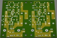
Notice that the groundplane is divided in sections.
One more option would be having extra resistors for the feedback. Sometimes it's very easy just to solder one resistor in parallel to trim the voltage.
not so smart now when you have put so much work into it... but... Why don't you make the pcb with a mirrored negative regulator so that the ground can be shared at the output? You can still make the pcb detachable. If you check my JSR06 PSU you can see what I mean. The advantage would be a true +-15 V PSU and in the same time to single boards.Notice that the groundplane is divided in sections.
One more option would be having extra resistors for the feedback. Sometimes it's very easy just to solder one resistor in parallel to trim the voltage.
Per,
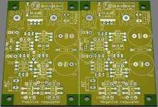
I don't see the point in mirroring the layout, when I have two identical sections providing a positive and negative supply. I like mirrored layouts, but only when there is a need for it due to mechanical considerations or signal flow. The layout is as close to identical as possible as I have used complementary parts everywhere possible / needed.
The gnd plane can be separated – no problem - I just thinks its going to be a forum decision so that most people will be happy with the choices made.
I added a multi turn trimmer to make adjustment easier.
An idea could be to piggybag the positive and negative supply to save space.
\Jens
- Status
- This old topic is closed. If you want to reopen this topic, contact a moderator using the "Report Post" button.
- Home
- Group Buys
- Scalable PSU/regulator GB