Thanks Gary, let me know my costs and I will forward you the funds. I believe I still have you setup at my bank from last time when I bought the weiner pcbs from you. Just need to confirm it is still correct.
I also started a Mouser project for the pro pcb. I see they have the Coilcraft inductors in stock and the IC's, just need to confirm the exact packages and of course the rest of the passive devices. I will complete once I get your Mouser BOM.
Cheers
Rick
I also started a Mouser project for the pro pcb. I see they have the Coilcraft inductors in stock and the IC's, just need to confirm the exact packages and of course the rest of the passive devices. I will complete once I get your Mouser BOM.
Cheers
Rick
Unfortunately you are but one man, gmarsh, and your skills are in demand.
Im interested in a stereo wiener pro (hopefully 1.0).
I took a look at the chinese 3eaudio amp and while it does look decent its not the quality I see from gmarsh projects, and I'll wait however long it takes for him to free up, my stereo wiener is fine until then")
some possibilities:
-raise prices a bit that its at least worthwhile for you to build them, and do a order for wiener pro stereo only, minimum 50 units or whatever like you said earlier and have the shop build them. As far as the output impedance config that may have to be done separately by you? High end audio gear can cost ridiculous amounts of money, and gmarsh deserves to be compensated well for doing the work to make this project happen.
-License the design to a reputable *Canada or US-based* small-medium sized audio company that fits your ideals. For example JDSLabs, known for selling the ODAC (also licensed from an open-source design originally).and their headphone amps, they have not yet had any speaker amps afaik and they have the expertise to build out a full device with a nice custom chassis and provide support for it. While I do prefer a board already set up in a chassis, the downside is it probably won't be transparent so people can see the board itself (this is the only board I would actually want to show off!).
I really like the designs youve built, I wish more people can experience what real quality sounds like. I bought 3 or 4 different TPA3116 amps of varying quality/price before I found the Wiener, and was surprised how much better sound it could get out of the same exact IC. Thanks again Gary for making this happen!
Im interested in a stereo wiener pro (hopefully 1.0).
I took a look at the chinese 3eaudio amp and while it does look decent its not the quality I see from gmarsh projects, and I'll wait however long it takes for him to free up, my stereo wiener is fine until then
some possibilities:
-raise prices a bit that its at least worthwhile for you to build them, and do a order for wiener pro stereo only, minimum 50 units or whatever like you said earlier and have the shop build them. As far as the output impedance config that may have to be done separately by you? High end audio gear can cost ridiculous amounts of money, and gmarsh deserves to be compensated well for doing the work to make this project happen.
-License the design to a reputable *Canada or US-based* small-medium sized audio company that fits your ideals. For example JDSLabs, known for selling the ODAC (also licensed from an open-source design originally).and their headphone amps, they have not yet had any speaker amps afaik and they have the expertise to build out a full device with a nice custom chassis and provide support for it. While I do prefer a board already set up in a chassis, the downside is it probably won't be transparent so people can see the board itself (this is the only board I would actually want to show off!).
I really like the designs youve built, I wish more people can experience what real quality sounds like. I bought 3 or 4 different TPA3116 amps of varying quality/price before I found the Wiener, and was surprised how much better sound it could get out of the same exact IC. Thanks again Gary for making this happen!
Hi Gmarsh,
Welcome back! My Wiener pro board has problem that it can't be powered on. No light, no sound. Can you help me to troubleshoot?
I've measured the voltage as following:
For U3 (+/-12v regulator)
p8(SW) =2.3V
p3,p3(VIN/UVLO) = 19v
p4(RON) = 0.69v
warm to hot (3x-4x degree)
L5 (the inductor) a bit hotter than U3
U6 (the microcontroller)
little warm
p1(vcc) = 1v (suppose 3.3v)
u3
p1=0.99v
p3=1.8v
Thanks!
Last edited:
Trying to troubleshoot.
I've de-soldered the op-amps, the voltage still not correct.
Then I de-soldered the +/- 12v switching regulator and R40 and feed +12v to R40 at the "raw12v".
Now the amp can be powered on, but it shows solid red led.
I switch it off, check the +12v and raw12v to ground. the +12v is shorted to ground, raw12v doesn't shorted.
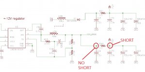
I checked the schematic, it seems that +12v is used by opamps only, and the raw12v is used by 3250. That's why I can power on the 3250, with 3.3v at the regulator, with red led and pop sound on right side of speaker.However, I still have not found the root cause of problem:
1. Where is the point that +12v is shorted to ground? I can see any issue on the PCB top and bottom yet...
2. Why is the amp turns to red led? If I connects the outputs to speakers, the right side speaker will make pop sound.
3. Why is it only the right speaker making pop sound but not both speakers?
I've de-soldered the op-amps, the voltage still not correct.
Then I de-soldered the +/- 12v switching regulator and R40 and feed +12v to R40 at the "raw12v".
Now the amp can be powered on, but it shows solid red led.
I switch it off, check the +12v and raw12v to ground. the +12v is shorted to ground, raw12v doesn't shorted.
I checked the schematic, it seems that +12v is used by opamps only, and the raw12v is used by 3250. That's why I can power on the 3250, with 3.3v at the regulator, with red led and pop sound on right side of speaker.However, I still have not found the root cause of problem:
1. Where is the point that +12v is shorted to ground? I can see any issue on the PCB top and bottom yet...
2. Why is the amp turns to red led? If I connects the outputs to speakers, the right side speaker will make pop sound.
3. Why is it only the right speaker making pop sound but not both speakers?
Attachments
Last edited:
It seems that the switching regulator was unable to output correct voltage because of the shorting at +12v. Now I separated the +12v and raw12v, the led can be lit, which means the microprocessor is working (with 3.3v). The 3250 is able to work as well. However, there's solid red led, which means something is wrong at the 3250, may be the output is shorted. I still can't find what makes it shows red light.
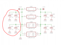
If the +12V (non-raw) net is shorted to ground, options are the LME49724's (the 49723's on the input don't have a direct connection to ground) or perhaps one of the decoupling capacitors on the 12V rail.
If you've got a current limited bench supply and a multimeter that has a millivolt setting, feed some current into the shorted rail (say 50-100mA) and measure the voltage across the decoupling caps by each of the op-amps. Wherever you measure the lowest voltage is probably where the short is. Also inspect the solder joints.
Removing the 49724's is a pain as they have a thermal pad underneath, ideally you'll need a hot air station to do it.
If you want, you could mail the board back to me and I'll have a go at it. I'll do cost of parts required plus 20 bucks CAD for time plus shipping.
@rsavas: PM me your mailing address and e-mail address for the mouser BOM. I'm ordering some parts on Tuesday and I'll get the microcontroller for your bare board.
Thanks Gmarsh,
I have hot gun and I have already desoldered all the four op amps and the switching regulator, the diode in -12v rail and the inductor.
Now it seems that finding the root cause of the over current warning (red led and pop on right side speaker) is the most concern as I don't need +12v but only raw 12v according to the schematic diagram. Is that true?
Finally found that one of the de-coupling caps is shorted...
Now all the caps in the +12v rail are removed, op-amps gone, only the microcontroller, 3250 and 3.3v ldo are kept.
However, the 3250 amp still showing red led.
It seems that there's something short at output of 3250, because it gets warm without any input and output attached. After turning on for 1 minute, the 3250 gets warm. I think this is not normal. Do you have any idea what should I check?
Attachments
Last edited:
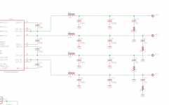
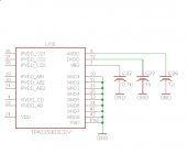
Power up the amp, measure the voltage at the INPUT_x pins of the TPA - they should all float up to a few volts (AVDD/2, I think).
Also measure the voltage on the AVDD pin, DVDD pins and Vbg pin.
If any of these things are zero, or not right, power off the amp and measure for shorts at any of these pins to ground. Could be a blown TPA chip, or it could be something external.
Also measure the voltage on the AVDD pin, DVDD pins and Vbg pin.
If any of these things are zero, or not right, power off the amp and measure for shorts at any of these pins to ground. Could be a blown TPA chip, or it could be something external.
Thanks Gmarsh.Power up the amp, measure the voltage at the INPUT_x pins of the TPA - they should all float up to a few volts (AVDD/2, I think).
Also measure the voltage on the AVDD pin, DVDD pins and Vbg pin.
If any of these things are zero, or not right, power off the amp and measure for shorts at any of these pins to ground. Could be a blown TPA chip, or it could be something external.
I found a problem here: INPUT_D is just few mV, all other INPUTs are 3.xV
Attachments
avdd=7.7v
dvdd=3.3v
vbg=1.2v
I just replaced the 3250, the red led is gone. Unfortunately, it doesn't make sound.
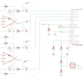
I checked the voltage at input A to D. Input A to C are all 3.9V, however, input D is just 2.5V. When I turn off the power (open the ENABLE pins). Input A to C are 0v, Input D is -1.2V. Moreover, the +12v regulator gets warmer than before the 3250 is replaced. So it seems there's something wrong, may be the pcb trace?
Input D shouldn't be capable of going to -1.2V, there's no negative voltage applied to the TPA. Unless something's screwed up in the front end op-amp stage making it drive negative voltage into the amp, and the film cap for that input is shorted.
Remove the four film caps and measure their resistance, which should be well up into the megohms. Leave them off the board, power the board up and measure voltage on both the analog-stage and TPA sides of the footprint.
Remove the four film caps and measure their resistance, which should be well up into the megohms. Leave them off the board, power the board up and measure voltage on both the analog-stage and TPA sides of the footprint.
Wiener PBTL and KEF LS50 Speakers
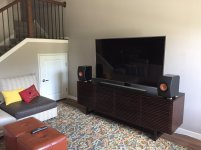
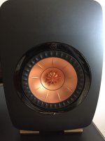
I've been away from this forum for some time as I've moved my family and home twice in 15 months in the spirit of career advancement. My current home is a modern townhome apartment in the Minneapolis, Minnesota suburbs, so space is rather limited and I had to put my beloved Klipsch Forte IIs in storage. For a few months, I was getting by with listening through my Sennheiser Momentum 2 wireless headphones and iPhone, but that was wearing thin fast.
While I was on vacation a few weeks ago, I had an opportunity to audition a pair of KEF LS50 bookshelf speakers, and I was impressed with the liveliness, accuracy and coherency of these compact monitors. Surely at 85dB sensitivity and an impedance curve that can dip down to 4 ohms couldn't possibly work with my Wiener TPA3118 PBTL amp powered with a modified Astron regulated linear power supply. Well, fast forward to this weekend, and I bought a pair of the KEF LS50 speakers, and hooked them up. Now I also use an Audio Research LS7 tube linestage with gain in front of my Wiener PBTL amp, and I am amazed at how loud this system can play.
I have doctormord's TPA3255 amp board, and I plan to build this amp with a more powerful power supply once I re-establish my DIY lab. I'd really like to hear these KEF's driven by a higher powered Texas Instruments Class D amp. For now, I am quite surprised and extremely pleased with the rich presentation I get with the Wiener/KEF combo. Thanks again gmarsh!
Attachments
- Status
- This old topic is closed. If you want to reopen this topic, contact a moderator using the "Report Post" button.
- Home
- Group Buys
- "The Wiener" TPA3118 amplifier, group buy #3 + "Wiener Pro" prototypes.