That's the single hand-soldered Pro that I made, the thermal pads were soldered from underneath with an iron hence the solder being present. No surprise that's the board with the problem.
Looks like one end of R14 isn't soldered properly, are you able to touch that up and retest?
Sent from my LG-D852 using Tapatalk
Looks like one end of R14 isn't soldered properly, are you able to touch that up and retest?
Sent from my LG-D852 using Tapatalk
That's the single hand-soldered Pro that I made, the thermal pads were soldered from underneath with an iron hence the solder being present. No surprise that's the board with the problem.
Looks like one end of R14 isn't soldered properly, are you able to touch that up and retest?
Sent from my LG-D852 using Tapatalk
R14 is soldered on, just not pretty. I also test with a meter. Anyways the problem is the with other channel.
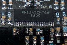
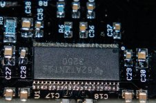
The joints look OK. Pins 6/7 of the TPA3250 are the input pins for the flaky channel, try poking on them with a toothpick or something else non-conductive and see if it changes the gain of the amp.
If that's not the problem, here's the procedure I'd do:
- Use a computer or some other audio source to make a 60Hz or similar test tone. Feed the same tone into both inputs.
- Use a DMM, set to AC measurement mode, to measure the audio input level at the input terminal blocks. Both should measure the same, which eliminates the input audio source as the issue.
- Note the four plated holes next to C46/C47/C48/C49, this is the output of the op-amp stage. You should measure the same values from "C46 hole" to "C47 hole" that you do from "C48 hole" to "C49 hole". Do this measurement and note the value.
- Additionally, measure from all four of the holes to ground. Use the GND test point or one of the four corners of the board as your ground reference. These measurements should all be the same, and should be 1/2 the measured value of the hole-to-hole measurement. Note the value.
If both of those measurements are OK, the issue isn't the input stage.
- Flip the board over, and measure the voltage from each of the TPA-facing ends of the four film capacitors to ground. These are the "inner" pins. You should measure the same value, if not, either one of R13 through R16 is bad, or one of the film caps itself is bad.
I'd also set your meter to DC voltage mode and measure the same nodes, you should see 2.x volts (or whatever the input voltage of the TPA chip is). If you don't see this, the TPA might be toast.
- Finally, with the meter back on AC mode, measure the voltage across each of the output channels, and from each side of each output channel to ground. Note the value.
I found an issue but I can't figure out the root cause, just want to share and see if any of you have similar experience.
When I mount the Pro board to the chassis, the status LED may turn to solid red. I use metal screws to mount them. I tried both power supply from the same chassis and thru external power source, it still shows red. Then when I unmount the card and hold it by hand, it shows green immediately. So there should be short circuit if I mount the card to the chassis.
When I mount the Pro board to the chassis, the status LED may turn to solid red. I use metal screws to mount them. I tried both power supply from the same chassis and thru external power source, it still shows red. Then when I unmount the card and hold it by hand, it shows green immediately. So there should be short circuit if I mount the card to the chassis.
Kenneth: Are you using standoffs? If the bottom of the board touches the case and it shorts the leads of the inductors or the output terminals, that'll cause the problem.
Maxx: I'm taking care of a few other projects around the house right now, I'll be back on Wiener stuff soon.
As it stands right now, I've got parts to build 2 8-ohm Pro's and 2 8-ohm PBTLs, but I haven't built those cards yet and I want to get them built/tested before I accept money from people. I'll start another group buy when I can get parts, right now the 8 ohm stereo inductors are out of stock at Mouser until May.
I guess that's the root cause. Anyway, I now mount the board on a wooden board and stick the wooden board to chassis. Now it is okay. ThanksKenneth: Are you using standoffs? If the bottom of the board touches the case and it shorts the leads of the inductors or the output terminals, that'll cause the problem.
Maxx: I'm taking care of a few other projects around the house right now, I'll be back on Wiener stuff soon.
As it stands right now, I've got parts to build 2 8-ohm Pro's and 2 8-ohm PBTLs, but I haven't built those cards yet and I want to get them built/tested before I accept money from people. I'll start another group buy when I can get parts, right now the 8 ohm stereo inductors are out of stock at Mouser until May.
")
Maxx: I'm taking care of a few other projects around the house right now, I'll be back on Wiener stuff soon.
As it stands right now, I've got parts to build 2 8-ohm Pro's and 2 8-ohm PBTLs, but I haven't built those cards yet and I want to get them built/tested before I accept money from people. I'll start another group buy when I can get parts, right now the 8 ohm stereo inductors are out of stock at Mouser until May.
Perfect, thanks Gary!
Got my amp in the mail on Thursday and finally installed the last component into my portable stereo box, thanks for the great board gmarsh
some more photos: Imgur: The most awesome images on the Internet
An externally hosted image should be here but it was not working when we last tested it.
An externally hosted image should be here but it was not working when we last tested it.
some more photos: Imgur: The most awesome images on the Internet
#28
Output power depends on the power supply voltage.
12V supply: 30W peak/15W RMS sine into a 4 ohm load. 15W/7.5W into 8 ohms.
24V supply: 120W peak/60W RMS into 4 ohms, 60W/30W into 8 ohms.
__________________________________________________________
May I know how to compute the amount of current needed for 30W at 24V supply for 8 ohms, 2 channels.
Is formula like : √[power in watts / R] x 2 channels = √[30/8] x 2 = 1.94A x 2 = 3.88A
Thanks
The joints look OK. Pins 6/7 of the TPA3250 are the input pins for the flaky channel, try poking on them with a toothpick or something else non-conductive and see if it changes the gain of the amp.
If that's not the problem, here's the procedure I'd do:
- Use a computer or some other audio source to make a 60Hz or similar test tone. Feed the same tone into both inputs.
- Use a DMM, set to AC measurement mode, to measure the audio input level at the input terminal blocks. Both should measure the same, which eliminates the input audio source as the issue.
- Note the four plated holes next to C46/C47/C48/C49, this is the output of the op-amp stage. You should measure the same values from "C46 hole" to "C47 hole" that you do from "C48 hole" to "C49 hole". Do this measurement and note the value.
- Additionally, measure from all four of the holes to ground. Use the GND test point or one of the four corners of the board as your ground reference. These measurements should all be the same, and should be 1/2 the measured value of the hole-to-hole measurement. Note the value.
If both of those measurements are OK, the issue isn't the input stage.
- Flip the board over, and measure the voltage from each of the TPA-facing ends of the four film capacitors to ground. These are the "inner" pins. You should measure the same value, if not, either one of R13 through R16 is bad, or one of the film caps itself is bad.
I'd also set your meter to DC voltage mode and measure the same nodes, you should see 2.x volts (or whatever the input voltage of the TPA chip is). If you don't see this, the TPA might be toast.
- Finally, with the meter back on AC mode, measure the voltage across each of the output channels, and from each side of each output channel to ground. Note the value.
I pull out the right side coupling cap and checked the voltage of the +/- input and got 3.89V on one and 11~70mV on the other.
I didn't check further as I think the TPA chip is shot
With the board powered off, set your meter to ohms and measure from the coupling cap input where you measured ~11mV to ground. Might be a short.
I'll build up another card and mail it to you. I'm out of 10uH inductors so I'll ship the board without them installed, you'll have to transplant them from that board.
I'll build up another card and mail it to you. I'm out of 10uH inductors so I'll ship the board without them installed, you'll have to transplant them from that board.
With the board powered off, set your meter to ohms and measure from the coupling cap input where you measured ~11mV to ground. Might be a short.
I'll build up another card and mail it to you. I'm out of 10uH inductors so I'll ship the board without them installed, you'll have to transplant them from that board.
I got no reading on the bad input (infinite R) and 142k on the 3.9v input. The other good channel got both 142k to ground, so I guess that confirms it.
Thank you very much. If you need the bad board back, I can ship it back to you. I can transplant the inductors from the bad board.
There is no hurry at all on this board as I brought a Pro board from another member who has given it up.
Also, please wait a bit to confirm that other members in my group buy do not have this problem. Fingers crossed.
LED off: amp is off (disabled, or unpowered)
Green LED: amp is running, all is good
Amber LED: amp is either clipping (blinking amber from time to time) or overtemperature warning is active (solid amber). Both warnings come out of the same /CLIP_OTW pin of the TPA3250.
Red LED: amp fault has occurred. Either overcurrent protection kicked in (in which case the amp will flash green/red and you'll probably hear pops coming out of your speakers) or the amp has reached the overtemperature shutdown threshold.
Hi Gmarsh,
I run the Pro for one day and it looks good. However, today I power off it and power on after about one minute, the speaker makes pop sound, and the led shows green/red flash, which means it triggers overcurrent protection.
I turned the volume to lowest (it was normal(low) volume), the LED goes to solid green again, but when I turn the volume up again, when there's little sound, it shows red/green flash again. Have you had such experience before?
Thanks
What are you using for a power supply? If its voltage is dropping out, that could trigger the "power cut" protection.
Shorting the enable input and switching the main power is fine.
I use sigma11, 25V AC primary, 24V DC secondary
The board now not showing any LED... Don't know what's happened.
#28
Output power depends on the power supply voltage.
12V supply: 30W peak/15W RMS sine into a 4 ohm load. 15W/7.5W into 8 ohms.
24V supply: 120W peak/60W RMS into 4 ohms, 60W/30W into 8 ohms.
__________________________________________________ ________
May I know how to compute the amount of current needed for 30W at DC 24V supply driving 8 ohms, 2 channels.
Is formula like : √[power in watts / R] x 2 channels = √[30/8] x 2 = 1.94A x 2 = 3.88A
Anyone can help please?
Thanks
- Status
- This old topic is closed. If you want to reopen this topic, contact a moderator using the "Report Post" button.
- Home
- Group Buys
- "The Wiener" TPA3118 amplifier, group buy #3 + "Wiener Pro" prototypes.