Has anyone found a U.S. in-stock source for the rotary switch? Mouser lists it, but with a very long lead time on backorder. I think I found an equivalent from Digikey, but that is also not in stock. Thanks - Pat
Try element14!
CK1051 - LORLIN - ROTARY SWITCH, 4, 30°, 150MA, 250V | Newark element14
Hi, My DAC is due to arrive later this week - then the fun begins! Is the assembled input board kit still available please? About to put order into Farnell for a few goodies...
Many thanks,
Andrew
Many thanks,
Andrew
There will be more boards available next week, feel free to sign up 🙂
Make sure you send me your paypal id in PM and specify which option you want.
Make sure you send me your paypal id in PM and specify which option you want.
Has anyone found a U.S. in-stock source for the rotary switch? Mouser lists it, but with a very long lead time on backorder. I think I found an equivalent from Digikey, but that is also not in stock. Thanks - Pat
The C&K Components switches such as this one: A30415RNCQ C&K Components | Mouser from Mouser should also fit. There are other C&K switches in the series that would work as well - just make sure they are 4 position, 3 pole, 1 deck type with PCB/though hole pins (not solder lugs which will not fit throgh the PCB holes).
Question, I am running my DAM with +/-12VDC and am finding that the regulator that only powers the TORX147L (at the moment, no LED's connected) is running well into the 70C territory. Is this supposed to be like this or am I doing something wrong? Whereas the 3.3V LDO regulator on the DAM is cool to the touch. Everything is otherwise working fine.
More boards are now available. To get them, please send me a PM with your paypal ID and specify which option you want (bare board/kit/assembled) and how many.
For those on the waiting list who have received and paid the Paypal invoices, the orders will be shipped by the end of this week.
For those on the waiting list who have received and paid the Paypal invoices, the orders will be shipped by the end of this week.
IMPORTANT error correction
IMPORTANT!
Version 1.1 of the input boards contain an error which causes the 3.3V regulator to run very warm. It can also have an effect on the power supply of the DAM1021 DAC and therefore slightly impact the sound quality.
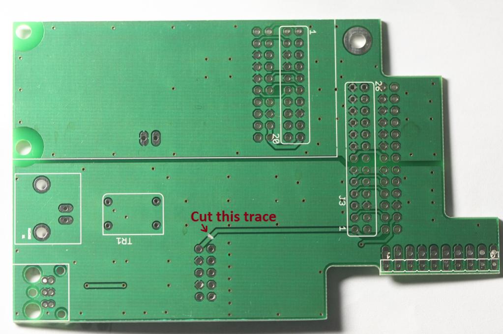
Even though the input board and the DAC are functional as is, it is strongly recommended to implement this fix. On the back side of input board cut the trace connecting the "front panel" connector to the J3 connector as shown in the picture. There are no other traces nearby that could be damaged, but make sure neither end of the cut trace gets shorted to the surrounding ground plane. That is all that needs to be done.
Those who do not feel comfortable doing it themselves, can mail the board to me and I will do the modification and send the board back free of charge.
All boards shipped from now on will have the fix already in place.
The initial prototype V1.0 boards did not have this error, users of those boards are not affected.
IMPORTANT!
Version 1.1 of the input boards contain an error which causes the 3.3V regulator to run very warm. It can also have an effect on the power supply of the DAM1021 DAC and therefore slightly impact the sound quality.
Even though the input board and the DAC are functional as is, it is strongly recommended to implement this fix. On the back side of input board cut the trace connecting the "front panel" connector to the J3 connector as shown in the picture. There are no other traces nearby that could be damaged, but make sure neither end of the cut trace gets shorted to the surrounding ground plane. That is all that needs to be done.
Those who do not feel comfortable doing it themselves, can mail the board to me and I will do the modification and send the board back free of charge.
All boards shipped from now on will have the fix already in place.
The initial prototype V1.0 boards did not have this error, users of those boards are not affected.
Last edited:
normundss: Isn't that the pwr-feed to the regulator? If so, where does it get power from now?
It gets it from the A+ lead, hence the point of the 3.3V regulator. What is happening is the DAM's onboard 3.3V supply is bridged to the output of this 3.3V regulator on the input board. DOH.
From what I see it was taking most of the 3.3V load of the dam, as the dam's onboard regulator ran cool to the touch.... which I thought was strange given it was always a bit warm during my initial test phase without the input board.
After performing this fix the onboard regulator is warmer while the input board regulator now runs cool...
Last edited:
Oh, is see... i'll cut these traces directly then myself. Luckily i haven't started my dac yet - it just sits waiting for me to finish some other projects before doing this one.
It gets it from the A+ lead, hence the point of the 3.3V regulator. What is happening is the DAM's onboard 3.3V supply is bridged to the output of this 3.3V regulator on the input board. DOH.
From what I see it was taking most of the 3.3V load of the dam, as the dam's onboard regulator ran cool to the touch.... which I thought was strange given it was always a bit warm during my initial test phase without the input board.
After performing this fix the onboard regulator is warmer while the input board regulator now runs cool...
DOH indeed... I had named both the DAM and the input board 3.3V power nets "+3.3V" on the schematic, thus they ended up being connected on the board. It does not produce an obvious fault, so took awhile to detect. I actually noticed that when DAM was powered by a TPS7A47 regulator in place of the stock 1117 and the input board was plugged in, sound became "dirtier" than without the input board. That got me thinking that something is not right. It is probably not very noticeable with unmodded DAM power supply.
Luckily it is very easy to fix and there are no other traces or components nearby that could be accidentally damaged.
Hi Normundss
I need to confirm the followings before I proceed:
It seems that the jumpers J4 on DAM1021 is preventing me from fitting the i/o board.
Should I remove them?
Second, in post #127 of this thread, the first picture shows that the board is not connect to all the power pins in J2. Does it matter to connect all of them (most of them are GND pins)?
Hmm, not sure what the problem is here. J4 looks like a JTAG header used for programming and testing the FPGA, so there should not be any jumpers on it. I don't have any jumpers on J4, and the height of the J4 header is about half the height of J2/J3, so it does not prevent mounting even when the optional pin headers are inserted on top of the input board. This is how it fits on my unit:Hi Normundss
I need to confirm the followings before I proceed:
It seems that the jumpers J4 on DAM1021 is preventing me from fitting the i/o board.
Should I remove them?
Second, in post #127 of this thread, the first picture shows that the board is not connect to all the power pins in J2. Does it matter to connect all of them (most of them are GND pins)?
All the pins on J2 can be connected, but only three pins are actually required. It is necessary to connect PWR A+, PWR +1.2V and at least one GND pin. I recommend installing a 10 pin connector strip and connecting all pins to avoid mistakes. The reason they are not connected in my prototype picture is that I simply did not have a big enough piece of female 2.54mm connector available on the weekend that I built it. Had to break in half the little piece that I had to be able to connect the really required pins 🙂
Do make the board modification described in post #152, that is quite important.
Attachments

Thank you normundss.
I managed to find a pair of longer pins head in my part bin.
The problem solved.
I managed to find a pair of longer pins head in my part bin.
The problem solved.
- Home
- Group Buys
- Input and switch boards for Soekris DAM1021 DAC