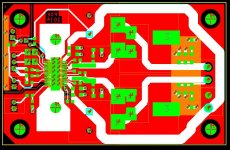
I have added the snubber directly on the outputs as in the ap note.
The R is 1206 and the C is 0805. (I am not using 0603 on this board)
Also probably the last change:
Avcc has been separated with a series R and bypass cap. (both 0805)
This will allow people to at least try this mod without hacking up the board. Anyone that does not wish to use it can either jumper the resistor or connect all three pins on the IC together.
")

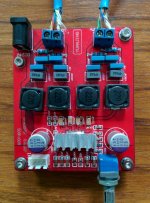
Here is what it looks like so far.
Would it be possible for your design to accommodate the use of the following 1210 smd bootstrap caps?
C3225X7R2E224K200AA TDK | Mouser
I believe that they help improve the quality of the sound quite a bit. At least that has been my experience with the red YJ board.
If so I would be interested in two boards.
Thanks.
Attachments
Would it be possible for your design to accommodate the use of the following 1210 smd bootstrap caps?
...
I believe that they help improve the quality of the sound quite a bit. At least that has been my experience with the red YJ board.
If so I would be interested in two boards.
Thanks.
Not by changing the footprint.
I do not want the bootstrap traces any longer than they already are.
I do not have room for 1210's and do not want to put them on the bottom...I like a good ground plane underneath.
However,
I will make expose the copper on the output traces and you could stand them up and use small wires down to the 0805 pads.
Would you be interested in a couple of boards under those conditions?
Doug
Last edited:
Not by changing the footprint.
I do not want the bootstrap traces any longer than they already are.
I do not have room for 1210's and do not want to put them on the bottom...I like a good ground plane underneath.
However,
I will make expose the copper on the output traces and you could stand them up and use small wires down to the 0805 pads.
Would you be interested in a couple of boards under those conditions?
Doug
Sounds like that could work. Please put me down for two boards. Thanks.
PBTL board, etc.
So far I have:
hajj 4 IC supplied
rafalkac 9+1free
goocher89 1
randytsuch 2
johnnygrace 2
ambiance 2 IC installed
DarpMalone 4
wushuliu 2
kelargo 3 IC installed
tabarddn 6 kit
afoor 2
col_s 2
matt_garman 2 IC installed
hui13 2
Total 44 boards
If there are any errors, please let me know.
Doug
So far I have:
hajj 4 IC supplied
rafalkac 9+1free
goocher89 1
randytsuch 2
johnnygrace 2
ambiance 2 IC installed
DarpMalone 4
wushuliu 2
kelargo 3 IC installed
tabarddn 6 kit
afoor 2
col_s 2
matt_garman 2 IC installed
hui13 2
Total 44 boards
If there are any errors, please let me know.
Doug
Here is what it looks like so far.
Please use insulated (from GND) mounting holes as now audio GND will always be connected with chassis causing a ground loop when a SMPS with PE connected is used. I had this so many times with class D amps fed by SMPS that I got used to mount the amp boards on an aluminium sheet that is screwed to the metal case by means of insulated stand offs
Metal cased SMPS always need to have PE connected for safety, getting rid of EMI etc. but ground loops are included for free.Even if one wants to connect audio GND to PE (why?) it would have to be done a more rigid way by wiring the PSU GND to chassis and PE, not by using mounting holes as conductors. It could be that I am mistaking but that's how it looks on the picture.
Last edited:
Please use insulated (from GND) mounting holes
...
Done.
+1 for thisThanks, you're doing the others and yourself a favor. Now 2 of those on one board please
Thanks, you're doing the others and yourself a favor. Now 2 of those on one board please
Just to be clear.
Are you requesting a change or ordering two boards joined together?
If so, do you want the ground plane connected between the two?
I could do that.
birca1987, the same questions.
Have to go for a bike ride now.
Later,
Doug
Last edited:
DUG, there seem to be further developments on the main TPA3116 thread, do you think it worthwhile awaiting the outcome of some of these discussions before finalising your board?
Good idea, IMO.
I'm very tempted to put my name down for 2 boards - IC soldered, but I would like to see where this goes first.
I have been following the TPA3116D2 Amp thread for a very long time now and this board is coming together now.
Features, etc.
The power and speaker output can be connected with Weidmuller, Wieland, or other types with 0.2” (5.08mm) centres (holes are 0.051”…1.3mm) (or direct wire)
Mounting holes for a 3116 top heatsink or solder to the board 3118 type (14 vias)
Input caps are 0805/1206/1210/through-hole @0.1"LS/0.037" holes.
Power electrolytics are 0.65"dia/0.3"LS mainly to accommodate higher output powers.
Power supply HF bypass are 1206. (2 each side)
Inductor footprint will take at least 5 different types and also has two sets of through holes.
Filter and snubber footprints (top side) are 1206 with exposed copper on the bottom ground plane for other larger parts.
Exposed copper below the input area for ground plane extension for those using really large input caps.
Startup mute circuitry.
There is an option for the IC to come supplied. ($CDN7) 22 asked
There is an option for the IC to come soldered. ($CDN7) 9 asked
I am also putting together a Kit for a basic "get it running" level. (price TBD at this time) 8 asked
I have added the snubber directly on the outputs as in the ap note. The R is 1206 and the C is 0805.
Avcc has been separated with a series R and bypass cap. (both 0805)
Bootstrap caps are 0805 but I have exposed the copper on the output traces for 1210's and you could stand them up and use small wires down to the 0805 pads.
Insulated (from GND) mounting holes.
Pairs of boards could be ordered with a common ground plane.
I am panelizing the board this week and should be able to order on the weekend or early next week.
Then I will be working on the parts list and a kit.
Doug
Last edited:
Just to be clear.
Are you requesting a change or ordering two boards joined together?
If so, do you want the ground plane connected between the two?
I could do that.
birca1987, the same questions.
Have to go for a bike ride now.
Later,
Doug
Yes, the mono listeners are the minority nowadays
Even multichannel listeners need pairs of amps. You could just copy 2 boards on one large board but joining the GND plane is OK too. I guess not many will build mono blocks with each its own power supply. Think of easy encasing with the least possible wiring and the least possible connections. Just 4 mounting holes necessary...The KISS approach again, it keeps working If you make one stereo board please try to keep input connectors at one spot (opposite to the power connector) for better wire routing. Just one power connector but with pads for separate power supply chokes to each channel would be nice. I now feel the separation coils make a difference. I know as I tamed the YJ blue Danzz board. RF everywhere...
Last edited:
- Status
- This old topic is closed. If you want to reopen this topic, contact a moderator using the "Report Post" button.
- Home
- Group Buys
- GB for TPA3116/8 PBTL bare pcb