Huh, this does not sound good
Yes, I put pacificsemi since I found there required jfet. Do you have any other source to recommend?

how about FET Audio | Hi-End Audio Projects
Hi Prasimix,
I'm a bit late to this thread and I'm not sure you would entertain some suggestions regarding your pcb layout of post #22 above, and particularly the ground tracking in both the gain section and the supply area - there's a few simple things in the active area to separate the signal ground from the supply grounds (C1, 2, 4, 5) but the power supply has the charging currents and the post filter/reg ground tracks all mixed up and could benefit in some component re-arrangement there, (IMO naturally!)
I'm a bit late to this thread and I'm not sure you would entertain some suggestions regarding your pcb layout of post #22 above, and particularly the ground tracking in both the gain section and the supply area - there's a few simple things in the active area to separate the signal ground from the supply grounds (C1, 2, 4, 5) but the power supply has the charging currents and the post filter/reg ground tracks all mixed up and could benefit in some component re-arrangement there, (IMO naturally!)
The Farnell BF862 in the BOM is an SMD device -- not through hole.
Yes, BF862 is only available as SMD. There is a room on PCB for both SMD and through hole. For later should be used solution suggested in main thread (please check post #232).
Hi Prasimix,
I'm a bit late to this thread and I'm not sure you would entertain some suggestions regarding your pcb layout of post #22 above, and particularly the ground tracking in both the gain section and the supply area - there's a few simple things in the active area to separate the signal ground from the supply grounds (C1, 2, 4, 5) but the power supply has the charging currents and the post filter/reg ground tracks all mixed up and could benefit in some component re-arrangement there, (IMO naturally!)
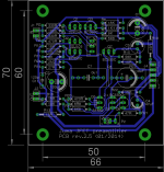
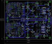
Yes, it's possible. Please find below new layout for single and dual channel version.
Attachments
Getting there - looking much better
On the left photo layout, R12 belongs to C2 GND (can move it below R11), same thing for R8 (shift to C1 GND), and also R17 (shift to below R22 - a bit of a squeeze but shorter track anyway)
On the combined power supply version, it's not so easy but start with making the central ground point adjacent to C16, C22 - this means the floating GND network (Thermistor, diodes) to be connected here also.
The main filter caps have a common GND point that includes the J8 connection to the transformer then has a single track to the new central earthing point near the C16, C22 caps that include the C17, C21 - as there's a bit of room here, I'd run separate tracks for the gnd pins on the regulators.
Not enough room to include the GND Lift thermistor (and diodes) but no real problem if off brd.
On the active circuit, if you exchange R6 for R9 and tie the gnd connection of R17 to the C1 cap, it leaves R8, and R12 to go to 'non signal gnd' - R8 can be relocated lower and easy to go to point on C1 also and the R12 can be moved about the P1 area and the gnd track fed thru there - a bit of 'jiggery pokery' but quite manageable.
I don't know if these alterations will bear any significant improvements to the final product but it's a pretty standard way of separating the signal ground connections from the power circuit grounds.
And, it's just my opinion - there's always other, and quite possibly better, ways of doing board layouts and we all can learn from your efforts.
Also, could you add me to your GB list for one preamp only pcb, plus a power supply version (as per above designs) on your GB site, if you would - thanks.
@ Tinitus .. so the k246 and j103 are the V grades that are easily available ?
The k246 and j103 only in BL available from Toshiba.
IDSS classification Y: 1.2~3.0 mA, GR: 2.6~6.5 mA, BL: 6~14 mA
br
ahh ...
sounds like I have no clew
but what is new

Hi. I would also be interested in one set of pcbs for the preamp. I could not find where I could add myself to the group buy, but count me in please! Thanks.
Thanks palmito, I added you on the list for 2 x single channel + 1 PS PCB. Please let me know if I missed something.
Thanks!Thanks palmito, I added you on the list for 2 x single channel + 1 PS PCB. Please let me know if I missed something.
Getting there - looking much better
On the left photo layout, R12 belongs to C2 GND (can move it below R11), same thing for R8 (shift to C1 GND), and also R17 (shift to below R22 - a bit of a squeeze but shorter track anyway)
On the combined power supply version, it's not so easy but start with making the central ground point adjacent to C16, C22 - this means the floating GND network (Thermistor, diodes) to be connected here also.
The main filter caps have a common GND point that includes the J8 connection to the transformer then has a single track to the new central earthing point near the C16, C22 caps that include the C17, C21 - as there's a bit of room here, I'd run separate tracks for the gnd pins on the regulators.
Not enough room to include the GND Lift thermistor (and diodes) but no real problem if off brd.
On the active circuit, if you exchange R6 for R9 and tie the gnd connection of R17 to the C1 cap, it leaves R8, and R12 to go to 'non signal gnd' - R8 can be relocated lower and easy to go to point on C1 also and the R12 can be moved about the P1 area and the gnd track fed thru there - a bit of 'jiggery pokery' but quite manageable.
I don't know if these alterations will bear any significant improvements to the final product but it's a pretty standard way of separating the signal ground connections from the power circuit grounds.
And, it's just my opinion - there's always other, and quite possibly better, ways of doing board layouts and we all can learn from your efforts.
Also, could you add me to your GB list for one preamp only pcb, plus a power supply version (as per above designs) on your GB site, if you would - thanks.
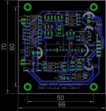
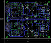
Thanks once again jameshillj for valuable suggestions. Please find below what I succeed until now. I'm not so sure what to do on PS section of dual channel version: you'd like to introduce diodes and varistor that belong to "gnd loop breaker"? In that case we also need one more terminal for earth connection.
Attachments
- Status
- This old topic is closed. If you want to reopen this topic, contact a moderator using the "Report Post" button.
- Home
- Group Buys
- Juma's LSK Preamp - through hole version