Hmmm.I´ve been soldering the psu now and I have 2 smd parts left but 3 places to put them,1 is marked R1 so that is right but is both R2 and c13 used in this construktion?And is c13 just paralell to some elyt??
Edit:Messaured the resistor and it was R2,should I just leave c13 out?
Edit:Messaured the resistor and it was R2,should I just leave c13 out?
Last edited:
Hi,
I received my package today and the pcbs are already stuffed and working well, only the balanced function has to be tested tomorrow.
@Ryssen
I don`t know if it is a good idea to leave C13 unstuffed, but the circuit works without it
If it is really needed, somebody should post a value for c13.
Arno
I received my package today and the pcbs are already stuffed and working well, only the balanced function has to be tested tomorrow.
@Ryssen
I don`t know if it is a good idea to leave C13 unstuffed, but the circuit works without it
If it is really needed, somebody should post a value for c13.
Arno
Hi, C13 is just an extra decoupling cap. I did the layout and added it for final testing of the PSU just like Cled. Point is that the boards haven't arrived at my place yet. Subbu build the first ones and they work as they should without C13. The power of old bipolar chips Adding C13 won't harm either...0.1 to 1 uF 25 V should do.
necplusultra, can't remember any promise but Subbu should mail schematics to every PSU board buyer.
Adding C13 won't harm either...0.1 to 1 uF 25 V should do. necplusultra, can't remember any promise but Subbu should mail schematics to every PSU board buyer.
Last edited:
J.P: see post number 4
He is waiting for the schematic, I think Subbu might being work on a build guide, donot warry, it will be here soon.
He is waiting for the schematic, I think Subbu might being work on a build guide, donot warry, it will be here soon.
I was about to ask about the build guide too, wanted to make sure I wasn't left off an email that sent it out.
Guess I need to wait a little while longer for it.
So since my board is on it's way I made a Mouser BOM, and found the tamura transformer is on backorder.
I think this is a cross
F16-150 Triad Magnetics | Mouser
Anybody care to double check?
I think this is a cross
F16-150 Triad Magnetics | Mouser
Anybody care to double check?
So since my board is on it's way I made a Mouser BOM, and found the tamura transformer is on backorder.
I think this is a cross
F16-150 Triad Magnetics | Mouser
Anybody care to double check?
Hello Randy
The transformer is available in digikey.com as well. Here is the link
3FD-316 Tamura | MT2106-ND | DigiKey
Cheers!
Subbu
Thanks Subbu for posting BOM and schematics.
works well for me powering one dac board without spdif input circuit.
the c13 does make it more stable and constant at 4.94x V.
tried a dummy load pulling about 290ma but could not get stable voltage.
what is the max current output from this psu board?
Is it possible to get more current with stable 5V voltage.
Last edited:
Hi it is a 250 mA 5 V power supply with current limiting. Changing the 2.2 Ohm (see datasheet of LM723) is possible but we did not limit current without a reason. The transformer is the limiting factor as it can supply 300 mA nominally. Our goal is to have a safe and low noise supply for our DAC boards, not to have burnt transformers etc. I already got mail if it can be used for Squeezebox devices but since I have none I can not tell what the current draw of such devices is.
Design parameters:
- The PSU should be small and able to supply low noise power to 2 x Subbu DAC boards
- Current should be limited in case a short appears or a DAC board fails to protect the transformer. We don't like fire in devices.
- No excessive 115 V/230 V wiring as not everyone is experienced with mains operated stuff
- the PSU should be suitable for either 115 V or 230 V mains voltage areas
I don't recommend changing the 2.2 Ohm resistor. I would recommend a small heatsink on the BD140 when powering 2 DAC boards (i.e. a balanced DAC configuration). Of course it will not hurt to use a small L shaped pieces of aluminium on the BD140 even when you only use 1 DAC board. Just make sure it will not short the BD140's lead wires.
The comment on C13 surprises me. Since I haven't received my PSU PCB's (of the final version) yet I will have to wait to check that. I added C13 for testing the final version and I added Cled for fun to those that fear noise from LEDs Point is that my luck is that I receive my boards later than most of you guys.
Design parameters:
- The PSU should be small and able to supply low noise power to 2 x Subbu DAC boards
- Current should be limited in case a short appears or a DAC board fails to protect the transformer. We don't like fire in devices.
- No excessive 115 V/230 V wiring as not everyone is experienced with mains operated stuff
- the PSU should be suitable for either 115 V or 230 V mains voltage areas
I don't recommend changing the 2.2 Ohm resistor. I would recommend a small heatsink on the BD140 when powering 2 DAC boards (i.e. a balanced DAC configuration). Of course it will not hurt to use a small L shaped pieces of aluminium on the BD140 even when you only use 1 DAC board. Just make sure it will not short the BD140's lead wires.
The comment on C13 surprises me. Since I haven't received my PSU PCB's (of the final version) yet I will have to wait to check that. I added C13 for testing the final version and I added Cled for fun to those that fear noise from LEDs
Point is that my luck is that I receive my boards later than most of you guys.
Last edited:
thanks Jean PAul,
was wondering if I can get .5a out of this to power hifiduino as I like the size of this psu. Obviously, the tfo must be more powerful for such current.
I didn't have the BOM fuse but I did put a .5a 120v ptc fuse until the BOM fuse are ordered.
love the sound of the dac. I2s fed from amanero board. Was previously using salas shunt but I find the footprint too large for this baby.
thanks again. looking forward to V3...
With a larger transformer you can supply 0.5 A. I guess it should be an off board transformer then or maybe a 5 VA version exists that fits on the board ? When using an off board transformer please use safe wiring to the PCB or go straight from the transformers primaries to the fused IEC receptacle.
Now you do the math for the current limiting resistor PCB tracks are quite wide but we havent tested the PCB for 1 A (or more) for instance. You are on your own trying stuff out.
Now you do the math for the current limiting resistor
PCB tracks are quite wide but we havent tested the PCB for 1 A (or more) for instance. You are on your own trying stuff out.
Last edited:
Hi All
I think to be abble to post some informations next week about PSU.
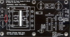
Received and built 2 units working perfectly (no Cled installed).
For guys using 220/240v, add a jumper to the transfo primary as shown in the attached pic
I started to get me out of my worries, so I hope to be back soon.
Regards
Phil
Transfo : http://fr.mouser.com/ProductDetail/Tamura/3FD-316?qs=dKoSqUwwxaUCRvKZ6GrcyVjlUiStth5c
Available 17th December 2012...
I think to be abble to post some informations next week about PSU.
Received and built 2 units working perfectly (no Cled installed).
For guys using 220/240v, add a jumper to the transfo primary as shown in the attached pic
I started to get me out of my worries, so I hope to be back soon.
Regards
Phil
Transfo : http://fr.mouser.com/ProductDetail/Tamura/3FD-316?qs=dKoSqUwwxaUCRvKZ6GrcyVjlUiStth5c
Available 17th December 2012...
Attachments
Last edited:
- Status
- This old topic is closed. If you want to reopen this topic, contact a moderator using the "Report Post" button.
- Home
- Group Buys
- Power Supply PCB for ES9023 / WM8804 S/PDIF DAC Group Buy