Hi WK,
Just received the PCB and started work by going thru the BOM and schematic but seem like some of resistor value on the schematic is somewhat different from the BOM. Is there a updated schematic available?
Thanks
BoM for one PCB
4x 10R 0.5% SMD 0805 Digikey RR12Q10DCT-ND
6x 100R 0.5% SMD 0603 Digikey RR08P100DCT-ND
2x 0R SMD 0603 Digikey P0.0GCT-ND
2x 10k 0.5% SMD 0603 Digikey RR08P10.0KDCT-ND
2x 470R 0.5% SMD 0805 Digikey RR12P470DCT-ND
4x 220µF 25V Digikey P10271-ND
2x 150pF 16V PPS SMD 0603 Digikey PCF1461CT-ND
2x 18mH 5%, matched to 1% Mouser 434-02-183J
http://www.diyaudio.com/forums/grou...hard-filter-buffer-es9022-11.html#post3113690
The orginal schematics
http://www.diyaudio.com/forums/digi...ng-new-ess-vout-dac-es9022-7.html#post2867664
syklab, I don't have the datasheet close at hand right now but from memory the first part of the schematic is the datasheet output filter which is assumed to be on the DAC board, it is on the xen audio ES9022 boards and also acko's ES9023 boards. I'm not familiar with details of other implementations of the ES9023 DACs.
I'd rather EUVL or WK or JG confirm components for other positions as I don't wish to lead you astray. Though I *think* 10k is for R4 and R5 represents the internal resistance in the inductor ...
Chris
I'd rather EUVL or WK or JG confirm components for other positions as I don't wish to lead you astray. Though I *think* 10k is for R4 and R5 represents the internal resistance in the inductor ...
Chris
Last edited:
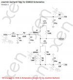
Attached is the (original) schematics V3 according to which we built our prototype and made up the Bill of Material.
This is the exact circuit as on the PCB itself.
The following discrepancies exist between our schematics (V3) and that in the following link (version 3.1) :
http://www.diyaudio.com/forums/digi...ng-new-ess-vout-dac-es9022-7.html#post2867664
(the component designations below are according to the Joachim Gerhard schematics in the above link)
a) R6,C4 do not exist on the PCB, as they are part of the ES9023 DAC circuit.
b) R2, P1 are removed as we guarantee proper matching, and hence no need to trim DC offset.
c) R3 has been changed to 100R, and 2 additional gate stoppers added for the J111s.
d) R4 has remained 10k and not updated to 18.9k
This is identical to what we built, tested and then approved by Joachim.
Apart from the 10k/18.9k discrepancy, the bill of material remains correct.
You can count this one (R4 update) on me as my mistake.
And I'll see if we can send 200x 18.7k Susumu 0603 to Fran, before he sends them to everyone.
(18.9k is not stocked by Digikey.)
Hope it is clear,
Patrick
.
Attachments
Last edited:
Attached is the (original) schematics V3 according to which we built our prototype and made up the Bill of Material.
This is the exact circuit as on the PCB itself.
The following discrepancies exist between our schematics (V3) and that in the following link (version 3.1) :
http://www.diyaudio.com/forums/digi...ng-new-ess-vout-dac-es9022-7.html#post2867664
(the component designations below are according to the Joachim Gerhard schematics in the above link)
a) R6,C4 do not exist on the PCB, as they are part of the ES9023 DAC circuit.
b) R2, P1 are removed as we guarantee proper matching, and hence no need to trim DC offset.
c) R3 has been changed to 100R, and 2 additional gate stoppers added for the J111s.
d) R4 has remained 10k and not updated to 18.9k
This is identical to what we built, tested and then approved by Joachim.
Apart from the 10k/18.9k discrepancy, the bill of material remains correct.
You can count this one (R4 update) on me as my mistake.
And I'll see if we can send 200x 18.7k Susumu 0603 to Fran, before he sends them to everyone.
(18.9k is not stocked by Digikey.)
Hope it is clear,
Patrick
.
Hi,
According to the schematic that R4 is 100R and R1 is 10K. Is that correct ?
Best regards
Attached is the (original) schematics V3 according to which we built our prototype and made up the Bill of Material.
This is the exact circuit as on the PCB itself.
The following discrepancies exist between our schematics (V3) and that in the following link (version 3.1) :
http://www.diyaudio.com/forums/digi...ng-new-ess-vout-dac-es9022-7.html#post2867664
(the component designations below are according to the Joachim Gerhard schematics in the above link)
a) R6,C4 do not exist on the PCB, as they are part of the ES9023 DAC circuit.
b) R2, P1 are removed as we guarantee proper matching, and hence no need to trim DC offset.
c) R3 has been changed to 100R, and 2 additional gate stoppers added for the J111s.
d) R4 has remained 10k and not updated to 18.9k
This is identical to what we built, tested and then approved by Joachim.
Apart from the 10k/18.9k discrepancy, the bill of material remains correct.
You can count this one (R4 update) on me as my mistake.
And I'll see if we can send 200x 18.7k Susumu 0603 to Fran, before he sends them to everyone.
(18.9k is not stocked by Digikey.)
Hope it is clear,
Patrick
.
Hi Patrick
Thanks for the above info but I’m not part of the GB and finding it a little difficult to source those 18K9 resistors.
Any idea where I may find some?
Thanks
Digikey has 18.7k. I consider 1% deviation close enough.
The inductors will have more variations.
Patrick
Hi Patrick
Thanks for the Info on the 18K7 which I have just ordered from Digikey.
")
Yup those inductors
I needed a few to get a close matched pair.
Looking forward to hearing the Filter Buffer and grateful to WK for all of his hard work matching and soldering.

Thanks again
In case you're having trouble with the PDF, here is the same file in jpeg format.not sure why but i'm having problems opening your attachment.
---Gary
Attachments
I have sent out x100pcs of JG Filter module (with jfet installed) in 58 packets by registered air mail (except the two local packets in Hong Kong) today.
Thanks for your patience.
WK and Patrick,
Just wanted to let you know that the boards arrived in today's post. Transit time from Hong Kong to California was pretty speedy - just over 1 week. Thanks for all the hard work measuring, soldering, and testing to get these out the door.
---Gary
Joachim specified +/-15V.
Current is ~16mA per channel. It of course varies from JFET to JFET (Idss).
But if you allow 25mA per channel, it is in any case on the safe side.
I was told just now that the inductors also arrived at Fran's.
So happy building & listening.
Patrick
Current is ~16mA per channel. It of course varies from JFET to JFET (Idss).
But if you allow 25mA per channel, it is in any case on the safe side.
I was told just now that the inductors also arrived at Fran's.
So happy building & listening.
Patrick
Member
Joined 2006
FC,And hi Gary!
It's great to run into you here and good to see that you're still playing with DIY. I was looking at my old notes and see that it was 10 years (!!) since we met in NY. Say hello to everyone in HK.
---Gary
- Status
- This old topic is closed. If you want to reopen this topic, contact a moderator using the "Report Post" button.
- Home
- Group Buys
- Joachim Gerhard Filter Buffer for ES9022