The J-G Filter Buffer GB boards are still with WK for soldering matched jfets, to my understanding the only people who have heard it are Joachim, Patrick and a couple who posted in the ES9022 thread and had made their own boards.
Joachim and Patrick have decided that it is good enough to spend XEN Audio's time producing boards and providing matched jfets, IMO that's usually a sign that it is worthwhile.
Joachim and Patrick have decided that it is good enough to spend XEN Audio's time producing boards and providing matched jfets, IMO that's usually a sign that it is worthwhile.
Hi
I've ordered a JG buffer too, but inductors won't be available before Christmas...
See EUVL post here about this : http://www.diyaudio.com/forums/grou...roup-buy-jg-filter-buffer-11.html#post3150268
So we have enough time to close the GB and deliver Subbu's DAC V3")
I've ordered a JG buffer too, but inductors won't be available before Christmas...
See EUVL post here about this : http://www.diyaudio.com/forums/grou...roup-buy-jg-filter-buffer-11.html#post3150268
So we have enough time to close the GB and deliver Subbu's DAC V3
not working yet . . .
Greetings,
My Subbu DAC didn’t work right after I built it. I didn’t mess with it for a while because as I was busy with other stuff. I got back to it last night. I measured the voltages which korben69 posted. Thank you korben69 for that post! It was very helpful.
I found the voltage at pin 1 of U4 was ~3V (though it bounced around), and the output voltage (pin 5) was about 0. So I replaced it and measured the same voltages.
Then I figured that a low voltage at pin1 of U4 could be caused by low resistance across C16 or C17 to ground, or by a high resistance across L1. First, I replaced both caps and got the same measurement. Then I replaced L1. This time I measured 5V at pin 1 of U4, but I found that both L1 and U4 got super hot, so I turned off the power supply. So I’m guessing that L1 and maybe U4 were fried, but that was a symptom of something else wrong. They would probably fry again if I continued to apply voltage.
L2 was not hot, and voltages at all pins of U3, U5 and U6 were consistent with korben69’s post.
So now I’m thinking a short across C16, C17, C18, C19, C8, U4 or Q2 could cause too much current through L1 and U4. But I just replaced C16, C17,* C8 and U4. Does anyone have any suggestions? Or should I just keep removing things until L1 and U4 don’t heat up anymore, then start replacing things, measuring and feeling as I go?
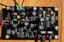
Also, I’m a little concerned that my C19, C22, C26 & C29 don’t look like the pictures in the data sheet, or in Skouliki’s, Skylab’s, or Tome’s photos. They may match Gary B’s photo. Ignore C8 in my photo. It was taken before I replaced it with the correct cap.
Greetings,
My Subbu DAC didn’t work right after I built it. I didn’t mess with it for a while because as I was busy with other stuff. I got back to it last night. I measured the voltages which korben69 posted. Thank you korben69 for that post! It was very helpful.
I found the voltage at pin 1 of U4 was ~3V (though it bounced around), and the output voltage (pin 5) was about 0. So I replaced it and measured the same voltages.
Then I figured that a low voltage at pin1 of U4 could be caused by low resistance across C16 or C17 to ground, or by a high resistance across L1. First, I replaced both caps and got the same measurement. Then I replaced L1. This time I measured 5V at pin 1 of U4, but I found that both L1 and U4 got super hot, so I turned off the power supply. So I’m guessing that L1 and maybe U4 were fried, but that was a symptom of something else wrong. They would probably fry again if I continued to apply voltage.
L2 was not hot, and voltages at all pins of U3, U5 and U6 were consistent with korben69’s post.
So now I’m thinking a short across C16, C17, C18, C19, C8, U4 or Q2 could cause too much current through L1 and U4. But I just replaced C16, C17,* C8 and U4. Does anyone have any suggestions? Or should I just keep removing things until L1 and U4 don’t heat up anymore, then start replacing things, measuring and feeling as I go?
Also, I’m a little concerned that my C19, C22, C26 & C29 don’t look like the pictures in the data sheet, or in Skouliki’s, Skylab’s, or Tome’s photos. They may match Gary B’s photo. Ignore C8 in my photo. It was taken before I replaced it with the correct cap.
Attachments
Resolder the chips with good 60/40 solder as the connections are substandard. You probably have a short between pins. C32 is soldered in the wrong way around.
I would start with cleaning the PCB and check the situation around the XO with a magnifying glass. What resistance do you measure over C8 ?
I would start with cleaning the PCB and check the situation around the XO with a magnifying glass. What resistance do you measure over C8 ?
Last edited:
Success!!!
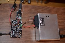
The problem was Q2, which is powered by U4. Though U4 may also have been a problem. A line of solder from at least one corner had climbed all the way up Q2 to the metal top. I replaced Q2 instead of just cleaning it up. I also cleaned up U3 and U4 with some wick. They look much better, and reversed C32. I'm listening to it right now, and I haven't even put C8 or C19 back yet. Sounds great as-is. I can't wait until I put it in a case and give it a better power supply. I'm currently using a Velleman kit.
Thank you everyone for your help. The second one, and V3 should go much more easily.
The problem was Q2, which is powered by U4. Though U4 may also have been a problem. A line of solder from at least one corner had climbed all the way up Q2 to the metal top. I replaced Q2 instead of just cleaning it up. I also cleaned up U3 and U4 with some wick. They look much better, and reversed C32. I'm listening to it right now, and I haven't even put C8 or C19 back yet. Sounds great as-is. I can't wait until I put it in a case and give it a better power supply. I'm currently using a Velleman kit.
Thank you everyone for your help.
The second one, and V3 should go much more easily.Attachments
This is what I expected. I am glad you found the problem and that you like the DAC. Give it some days, you will see that it will be even better then. Please solder C8 and C19 in place but I would like to advise to use new parts and not reuse the old ones as they might be overheated. Well, just assume they are not OK and replace them anyway as they are cheap. Change C8 for a tantalum 4.7 µF 10 V cap !!
Last edited:
Please check polarity of C8 if you will be using a tantalum cap. Since you heated the PCB a few times I guess it is the last chance before tracks will be peeling off.
Meanwhile I am starting to think that the "no individual support" remark can be deleted Please bear in mind that I will be moving houses next weeks and I won't be replying as much as I used to do. Also the rev. 3.X (or V3 as Korben calls it) has to be finished. Let's call it V3 for clarity's sake.
Meanwhile I am starting to think that the "no individual support" remark can be deleted
Please bear in mind that I will be moving houses next weeks and I won't be replying as much as I used to do. Also the rev. 3.X (or V3 as Korben calls it) has to be finished. Let's call it V3 for clarity's sake.
Last edited:
The problem was Q2, which is powered by U4. Though U4 may also have been a problem. A line of solder from at least one corner had climbed all the way up Q2 to the metal top. I replaced Q2 instead of just cleaning it up. I also cleaned up U3 and U4 with some wick. They look much better, and reversed C32. I'm listening to it right now, and I haven't even put C8 or C19 back yet. Sounds great as-is. I can't wait until I put it in a case and give it a better power supply. I'm currently using a Velleman kit.
Thank you everyone for your help.
Online Debugging Team Services ByronInLawrence, nice to read your V2.6 is working fine now.
As mentionned by Jean Paul, replace the suspected caps...
Hope you're enjoying the sound
Hi,
I was wondering if WM8804 + ES9023 be able to decode HDCD over SPDIF?
If I could get the output of HDCD over SPDIF and send it to this DAC using coaxial cable, is ES9023 be able to decode?
Tks.
Regards,
Tat
Hi Tat,
I have been playing HDCD from my oppo83se via s/Pdif and decode by Subbu DAC without any problem, the oppo s/Pdif outputs in LPCM.
Beautiful music from the first instant on. Chapeau, JP & Subbu!
Colors, depth, flow, reverb trails - both natural and machine made, detail, but not in a bad distracting way. Great human voices even soprano and choral with sheen, not edge. Power, drive and punch too, when it's there in the recording. Lovely, thank you. Crazy for the money.
Colors, depth, flow, reverb trails - both natural and machine made, detail, but not in a bad distracting way. Great human voices even soprano and choral with sheen, not edge. Power, drive and punch too, when it's there in the recording. Lovely, thank you. Crazy for the money.
Last edited:
I tried to add these comments to my earlier message, but it was too late to make more changes.
Modifications from the latest official build
I made all of these changes only because I didn't have the "official" parts handy any more when I was building. No listening or picking involved.
WIMA 6.8nF/63V caps at C14/C15 - Nichicon 100uF/25V UKW1E101MED cap at C10B - Vishay Sprague 4.7uF/25V aluminum organic cap 94SC475X0025CBP at C32 - good old Murata 1.0uF/50V X7R monolithic ceramic cap at C8. This last one was originally in the BOM before the tantaulum cap won out.
Listening Environment
Source - many
Power Supply - Texas Instruments TPS7A4700EVM-094 Evaluation Module. This thing is a great little power supply at a very extremely reasonable price.
Volume control – Funk Tonstudiotechnik Headphone Amp module. Some assembly required, but still amazing value for the money.
Speakers – Genelec studio monitors. A habit that is hard to break.
Hi grufti
Thank you for your report and comments
Reminder : Subbu's DAC V3 GB will be closed the 18th of October
Link : http://www.diyaudio.com/forums/group-buys/219672-es9023-wm8804-s-pdif-subbu-dac-v3-gb-interest.html
Thank you for your report and comments
Reminder : Subbu's DAC V3 GB will be closed the 18th of October
Link : http://www.diyaudio.com/forums/group-buys/219672-es9023-wm8804-s-pdif-subbu-dac-v3-gb-interest.html
Hi,
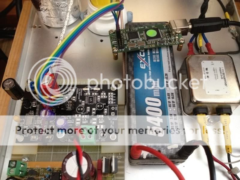
Worked on my second board with only the DAC part being filled and input from the Amanero USB to I2S interface. I use ADP151 3.3V for U4 and left the X7R ceramic cap there as per datasheet recommended. Made one mistake when building this module, an open connection was found on U3 pin 2 which cause the pin 5 ouput voltage dropped to half. Everything is working fine now, sound is smooth and detail. I am going to try it my other USB to I2S CM6631 board.
I am thinking about using a small break-out box to re-route the I2S signal from R7/R8/R9 to a switch so that I can switch between USB and S/pdif.
By the way, I bought a can of flux cleaner, works great!
Last edited:
- Status
- This old topic is closed. If you want to reopen this topic, contact a moderator using the "Report Post" button.
- Home
- Group Buys
- ES9023 / WM8804 S/PDIF DAC Group Buy