Do you think that prototyping is necessary?
I believe it would be a good strategy to prototype first, before ordering a large number of boards. Would it be possible to etch and test the board yourself?
What colour should the PCBs have?
I agree with meanman1964 that a black board and red silkscreen would be very nice.
/Mason
Mason,
the PCB must be double-sided with plated through-holes.
I cannot do this myself.
That is why I need a small number of "volunteers".
Best regards - Rudi_Ratlos
the PCB must be double-sided with plated through-holes.
I cannot do this myself.
That is why I need a small number of "volunteers".
Best regards - Rudi_Ratlos
The prototype PCB or multiple PCBs should be ordered up and the extra costs spread over the whole Group Buy.
You are checking that the PCB traces and pads are where they should be, you are not checking the sound quality.
If some Members volunteer to help out with more thorough stability testing of the prototypes then they should not pay the extra. They should pay the same price as everyone else in the GB, who should share all these extra costs. eg. posting the protos to you, then posting the protos to the volunteers.
The protos do not need to be screen printed, they do not need to be masked, they do not need to be gold dipped, etc.
If 100 PCBs cost $2000 and you spend an extra $30 on 6 protos and an extra $40 on postage then that extra $70 is shared out among 106PCBs @ $2070.
No body makes a profit.
No Member subsidises other Members.
No Member gets free samples.
There is one exception.
The PCB Designer could get a free sample (prototype) that is part of the design and deliver Group Buy of PCBs.
Some might even say the Designer gets a free sample of the finalised PCB for his efforts.
Last edited:
The prototype PCB or multiple PCBs should be ordered up and the extra costs spread over the whole Group Buy.
No body makes a profit.
No Member subsidises other Members.
No Member gets free samples.
I definitely agree. For the prototype boards, the cost should be spread across the group. This makes it inexpensive for everyone, and ensures that the final boards are correct. I don't mind waiting if the end result is successful.
/Mason
Rudi & Metal,
I think the boards should be kept the same colour (Red) as all your previous boards. They look superb and are easily recognisable as your work.
I also agree with AndrewT regarding the cost as this seems to be fair.
Well done you two.
Regards
Roy.
I think the boards should be kept the same colour (Red) as all your previous boards. They look superb and are easily recognisable as your work.
I also agree with AndrewT regarding the cost as this seems to be fair.
Well done you two.
Regards
Roy.
Last edited:
My friend METAL and I finished the layout of Mihai's RMI FC-100, and I will order 10 pcs of this PCB:
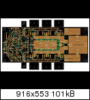
http://www.abload.de/img/fc-amp_cap35-gerbvh1o2l.png
in best quality: 2mm FR4-pcb, 2-layer, immersion Gold surface finish, this weekend.
We did not yet - during the protyping phase - concentrate on Mihai's PSU, but will use the common DXAmp +/- 35V - PSU
for the backend and a 7815/7915 -based resp. SALAS' shunt regulator based frontend PSU (+/-39VDC).
Fortunately I found 2 German DIYers who will accompany the prototyping.
I will keep you informed and will give you pictures / the status of our progress.
Best regards - Rudi_Ratlos
Last edited:
You know this could open an endless discussion 😉What colour should the PCBs have? Red, green or blue soldermask colour with white silkscreen or do you want something special for this AMP?
Black and white or white and Black?
PS: I vote for white 🙂
any news
Hello Rudi_Ratlos,
Do you have any infos about the PCB?
I'd be interested in 2-4 pieces depending on the price.
I've got all the parts for that beauty PCB
Best Regards,
Zsolt
Hello Rudi_Ratlos,
Do you have any infos about the PCB?
I'd be interested in 2-4 pieces depending on the price.
I've got all the parts for that beauty PCB
Best Regards,
Zsolt
Zsolt,
I ordered 10 pcs of this PCB on January, 17th.
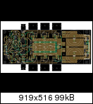
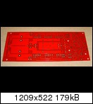
http://www.abload.de/img/fc_100_topviewqhecr.png
METAL and I decided to even include the rectifying section on the PCB.
There is no reason why not.
The size of a PCB is 190 x 74mm.
I expect the PCBs to be delivered in the course of the next week.
The delay is due to the Chinese "New Years holidays".
The price per PCB is 18€ .
The quality of the PCB is the best that you can imagine (Post #127).
The soldermask is red.
Four of these PCBs are reserved for METAL and me, who will do the prototyping.
I will offer the other 6 PCBs for sale.
I double-checked the layout twice and am absolutely sure, that I did not do any layout-error.
In case you are interested:
Do not waste your time and do a quick and dirty LM3X7 solution for the frontend PSU.
I layouted Mihai's frontend-shunt in the meantime:
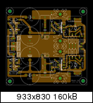
http://www.abload.de/img/fc-shunt7qe9m.png
and will receive the prototypes of the shunt tomorrow.
The shunt PCB is very compact: 76 x 73mm.
I can sell you the shunt-PCBs as well then (if you need).
Best regards - Rudi_Ratlos
I ordered 10 pcs of this PCB on January, 17th.

http://www.abload.de/img/fc_100_topviewqhecr.png
METAL and I decided to even include the rectifying section on the PCB.
There is no reason why not.
The size of a PCB is 190 x 74mm.
I expect the PCBs to be delivered in the course of the next week.
The delay is due to the Chinese "New Years holidays".
The price per PCB is 18€ .
The quality of the PCB is the best that you can imagine (Post #127).
The soldermask is red.
Four of these PCBs are reserved for METAL and me, who will do the prototyping.
I will offer the other 6 PCBs for sale.
I double-checked the layout twice and am absolutely sure, that I did not do any layout-error.
In case you are interested:
Do not waste your time and do a quick and dirty LM3X7 solution for the frontend PSU.
I layouted Mihai's frontend-shunt in the meantime:

http://www.abload.de/img/fc-shunt7qe9m.png
and will receive the prototypes of the shunt tomorrow.
The shunt PCB is very compact: 76 x 73mm.
I can sell you the shunt-PCBs as well then (if you need).
Best regards - Rudi_Ratlos
Hello Rudi_Ratlos,
the psu board looks good too. I'm interested in that too.
Mounting the rectifiers onto the pcb maybe good idea but i will use external rectifiers because want to add more capacitance (I'm megalomaniac). But it's not an issue to modify the board for that.
I'm not in a hurry. I'm laying in my bed with broken leg so have time. (at least 3-4 weeks)
If there's nobody who wants the boards and can test it before me i take 2-2 pieces otherwise i wait for the second round.
Best Regards,
Zsolt
Gentlemen,
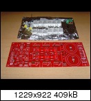
I received the PCBs of METAL's and my layout of Mihai's FC-100 AMP today.
I have ordered 10 PCBs.
The components side:
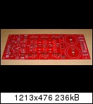
http://www.abload.de/img/joe0223ca9f.jpg
The solder side:
http://www.abload.de/img/joe027mayoc.jpg
The quality and precision of these PCBs is extraordinary and flawless.
I have a special offer for the first two of you, who will join and "prototype" this PCB.
A propos "prototyping":
The PCB follows exactly Mihai's schematics.
I added a DC blocking capacitor on the frontend (which can be easily de-activated by means of a jumper) and a diode-rectifier section
on the backend (that can be bypassed as well), and I am absolutely sure that I did not do any layout-error.
My 1st offer is:
http://www.abload.de/img/joe030w0bcd.jpg
- 2 FC-100 PCBs
- 12 matched (HFe, VBe, <5%) transistors NJL0281DG / NJL0302DG
- 12 Futaba MPC74 0R22 emitter resistors
- 2 Vishay MKP1839 1µF capacitor
- 2 Vishay MKT1828 3.3µF input capacitor
incl. wordlwide shipping for 80€.
2nd offer:
- same as above but without emitter-resistors for 74€.
Maybe somebody of you likes to "join the party".
Best regards - Rudi_Ratlos
I received the PCBs of METAL's and my layout of Mihai's FC-100 AMP today.
I have ordered 10 PCBs.
The components side:

http://www.abload.de/img/joe0223ca9f.jpg
The solder side:

http://www.abload.de/img/joe027mayoc.jpg
The quality and precision of these PCBs is extraordinary and flawless.
I have a special offer for the first two of you, who will join and "prototype" this PCB.
A propos "prototyping":
The PCB follows exactly Mihai's schematics.
I added a DC blocking capacitor on the frontend (which can be easily de-activated by means of a jumper) and a diode-rectifier section
on the backend (that can be bypassed as well), and I am absolutely sure that I did not do any layout-error.
My 1st offer is:

http://www.abload.de/img/joe030w0bcd.jpg
- 2 FC-100 PCBs
- 12 matched (HFe, VBe, <5%) transistors NJL0281DG / NJL0302DG
- 12 Futaba MPC74 0R22 emitter resistors
- 2 Vishay MKP1839 1µF capacitor
- 2 Vishay MKT1828 3.3µF input capacitor
incl. wordlwide shipping for 80€.
2nd offer:
- same as above but without emitter-resistors for 74€.
Maybe somebody of you likes to "join the party".
Best regards - Rudi_Ratlos
Gentlemen,
I received the PCBs of METAL's and my layout of Mihai's FC-100 AMP today.
I have ordered 10 PCBs.
The components side:
http://www.abload.de/img/joe0223ca9f.jpg
The solder side:
http://www.abload.de/img/joe027mayoc.jpg
The quality and precision of these PCBs is extraordinary and flawless.
I have a special offer for the first two of you, who will join and "prototype" this PCB.
A propos "prototyping":
The PCB follows exactly Mihai's schematics.
I added a DC blocking capacitor on the frontend (which can be easily de-activated by means of a jumper) and a diode-rectifier section
on the backend (that can be bypassed as well), and I am absolutely sure that I did not do any layout-error.
My 1st offer is:
http://www.abload.de/img/joe030w0bcd.jpg
- 2 FC-100 PCBs
- 12 matched (HFe, VBe, <5%) transistors NJL0281DG / NJL0302DG
- 12 Futaba MPC74 0R22 emitter resistors
- 2 Vishay MKP1839 1µF capacitor
- 2 Vishay MKT1828 3.3µF input capacitor
incl. wordlwide shipping for 80€.
2nd offer:
- same as above but without emitter-resistors for 74€.
Maybe somebody of you likes to "join the party".
Best regards - Rudi_Ratlos
Rudi,
I have interest in offer one


Rudi,
I am interested in your current offer. If by 'prototyping' , you mean that you would like someone to build quickly and report results, then it is likely that I won't qualify. Too many projects at hand.
Also, will you be offering more boards down the road?
Thanks,
Ryan
I am interested in your current offer. If by 'prototyping' , you mean that you would like someone to build quickly and report results, then it is likely that I won't qualify. Too many projects at hand.
Also, will you be offering more boards down the road?
Thanks,
Ryan
Vitalie,
thank you very much for your PAYPAL-transfer.
I will send you the components of my offer #1 tomorrow.
(The same applies to you, Patrick).
My offer #2 is still open.
I am currently thinking about the mechanical implementation of this AMP.
I will use what I have at hands:

http://www.abload.de/img/joe031znuaz.jpg
and like to install Mihai's shunt regulator and a speaker protection PCB (I will use a TRIAC - solution this time that will burn the fuse
in case of a DC / AMP defect, so that no relay will disturb the audio signal) on the heatsink as well.
I will keep you informed about my progress.
Best regards - Rudi
Attachments

- Status
- Not open for further replies.
- Home
- Amplifiers
- Solid State
- Roender's FC-100 prototype and builder's thread