All right...i will eat mine if you eat yours!
in other words..if mine beat yours...then you eat your amplifier....naturally the opposite will happens also.
Mine is not a class A.... think about....yours will be terrible to digestion.
But do not tell in this forum....that other amplifier was made by a very special guy...i do not want to hurt him...you can tell me using email.
deal made?
ahahahahahah!")
Carlos
in other words..if mine beat yours...then you eat your amplifier....naturally the opposite will happens also.
Mine is not a class A.... think about....yours will be terrible to digestion.
But do not tell in this forum....that other amplifier was made by a very special guy...i do not want to hurt him...you can tell me using email.
deal made?
ahahahahahah!
Carlos
Attachments

Last edited:
Board delivery date will be August 4
That's delivery from Colorado to me, in Kansas. Then I have to package them and ship them out.
Soon, I will post detailed pics of the board, though you won't see any difference between these, and the pics already posted unless you look really closely.
That's delivery from Colorado to me, in Kansas. Then I have to package them and ship them out.
Soon, I will post detailed pics of the board, though you won't see any difference between these, and the pics already posted unless you look really closely.
Last edited:
Byron, please, send your files imediately to Meanman
As you have files checked by manufacturer.
Meanman email is:
1964roovers@gmail.com
regards,
Carlos
As you have files checked by manufacturer.
Meanman email is:
1964roovers@gmail.com
regards,
Carlos
images from GERBERS
These images are from the manufacturer, Advanced Circuits, made from the gerbers I sent them.
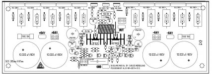
The board will be about 10.5" by 4.5". Copper and soldermask on one side. Silkscreen on the other. Green board with white silkscreen. Copper will be 1oz (0.35mm) thick. Copper tracks are left exposed along high current-carrying tracks for the builder to tin. That's what those long lines are in the soldermask. There are holes for terminal blocks, and for soldering directly to the board - your choice.
Carlos, maybe you could post the circuit diagram?
We'll be happy to answer any questions.
These images are from the manufacturer, Advanced Circuits, made from the gerbers I sent them.
The board will be about 10.5" by 4.5". Copper and soldermask on one side. Silkscreen on the other. Green board with white silkscreen. Copper will be 1oz (0.35mm) thick. Copper tracks are left exposed along high current-carrying tracks for the builder to tin. That's what those long lines are in the soldermask. There are holes for terminal blocks, and for soldering directly to the board - your choice.
Carlos, maybe you could post the circuit diagram?
We'll be happy to answer any questions.
Attachments
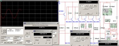
Here you have the schematic
It is not pretty...if someone wants to colaborate/cooperate and draw a better schematic (more pretty), then please, go ahead.
This was made using a simulator software.... NI Multisim 10 ... do not looks good.
This amplifier was not created using simulator...it was assembled and ideas tested and sonics tuned to each subcircuit... then finally was simulated.
I have assembled two prototypes and both prototypes played 300 hours for testing purposes.
regards,
Carlos
Attachments
Last edited:
Despite transistor printed into the circuit board and also in the schematic
are MJL3281 and it's counterpart, the suggested transistor, the really strong ones.... the reliable ones are these ones you see in the pdf....these are the ones i point as the stronger ones i could test at my home.
They have the same size (to264), but many other models can be used instead of these ones.... but my guarantee goes only to MJL4281A and MJL4302A.... you can substitute by its cousins...but do that under your own risk...there are several possible substitutions, and 2SC5200 and 2SA1943 are the most used ones...but all these are weaker compared to the ones i am pointing to you.
Sometimes speakers have strange impedance valleys (graphic) depending the frequency..this demands a lot of extra current to the power transistors.... and the ones i am suggesting are huge and will operate in the safe area.
regards,
Carlos
Attachments
Yes.... a mistake i think...i have asked Byron to fix that
I had problems because of "L" shape adaptor.... and board offering this option is dangerous...to this level of power we cannot have adaptors.
This may create a lot of troubles..we may have to use thermal protector and it switches the amplifier off when over heated...so...one more board...not a good idea.
See this video attached below..... i found that even using thermal grease, and also using thermal grease into "L" shape adaptor...even using Mica insulators together thermal grease i had troubles, and this amplifier shown is only 240 watts...imagine this monster we have here in this group buy?...that can put out 1 kilowatt (distorting)...will be a hell on earth.
Also i have used more screws to fix the adaptor.... no good result...when playing loud for long time i had the temperature going to around 65 degrées celsius..and this is dangerous... transistor junction will be very hot... several important specifications will change because of temperature.
Supercharged L adaptor heat transference issues - YouTube
I do think Byron is trying to offer this as option..as people can use it or saw the excess of board off... what i do not know is if people want to use their saw.... say... paying for boards that will need some work to be done on them.
regards,
Carlos
Attachments
Last edited:
Carlos, it is an awful work to saw off the excess of a 1.6mm (over even 2.0mm) thick fiberglass PCB. I tried it once and and failed. Maybe because I do not own the required tool.
I would not offer a choice how to mount the trasistors. Supply it for vertical mount only.
Best regards - Rudi_Ratlos
I would not offer a choice how to mount the trasistors. Supply it for vertical mount only.
Best regards - Rudi_Ratlos
Yes...it is not that easy to saw...people must have skills to do that
and to make it good looking we have to sand it using 120 grain sandpaper over a glass (flat surface)..... it is a really awfull work...very boring.
I have asked Byron to return to smaller board.
I had problems with adaptor:
http://www.youtube.com/watch?v=NchtCdxD5XM
http://www.youtube.com/watch?v=0lvs65yDmag
regards,
Carlos
Last edited:
- Status
- This old topic is closed. If you want to reopen this topic, contact a moderator using the "Report Post" button.
- Home
- Group Buys
- group buy for DX Blame MKIII Hx PCBs