jameshillj said:Sorry.
Be careful of what you wish for with a Protel wiz!
") Lets leave it that way. Won't hurt. Everybody! Have a second look for mistakes and we are on our way!
Lets leave it that way. Won't hurt. Everybody! Have a second look for mistakes and we are on our way!Very nice xaudiox, we all  appreciate your effort.
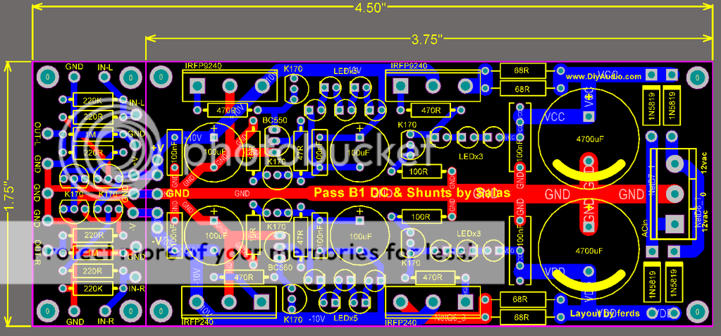
When I pointed out that the 100uF/25V should be 10 mm diam. 5 mm pitch to accomodate Elna Silmic II, I was referring only to the two o/p caps on the left, not to the ones in // with the led string in the middle of the pcb. Those colud be std caps (nobody will use $$$ caps in that position), that means 6.3 mm diam. 2.5 mm pitch for 100 uF/16 or 25 V. The bypass caps in // are also redundant.
P.S. Jameshill's idea to put the central ground track on the bottom side (blue) is also very good. If you do this, you can even move the gate stopper of the left IRPF240 further to the right, alligning the right pad to the TO92 placed nearly the pcb edge.
For simmetry sake, you can also allign the two 100 R that go to gnd (near "salas" on the silkscreen) to the 470 R gridstopper (move them a bit to the right)
appreciate your effort. When I pointed out that the 100uF/25V should be 10 mm diam. 5 mm pitch to accomodate Elna Silmic II, I was referring only to the two o/p caps on the left, not to the ones in // with the led string in the middle of the pcb. Those colud be std caps (nobody will use $$$ caps in that position), that means 6.3 mm diam. 2.5 mm pitch for 100 uF/16 or 25 V. The bypass caps in // are also redundant.
P.S. Jameshill's idea to put the central ground track on the bottom side (blue) is also very good. If you do this, you can even move the gate stopper of the left IRPF240 further to the right, alligning the right pad to the TO92 placed nearly the pcb edge.
For simmetry sake, you can also allign the two 100 R that go to gnd (near "salas" on the silkscreen) to the 470 R gridstopper (move them a bit to the right)
Hi,
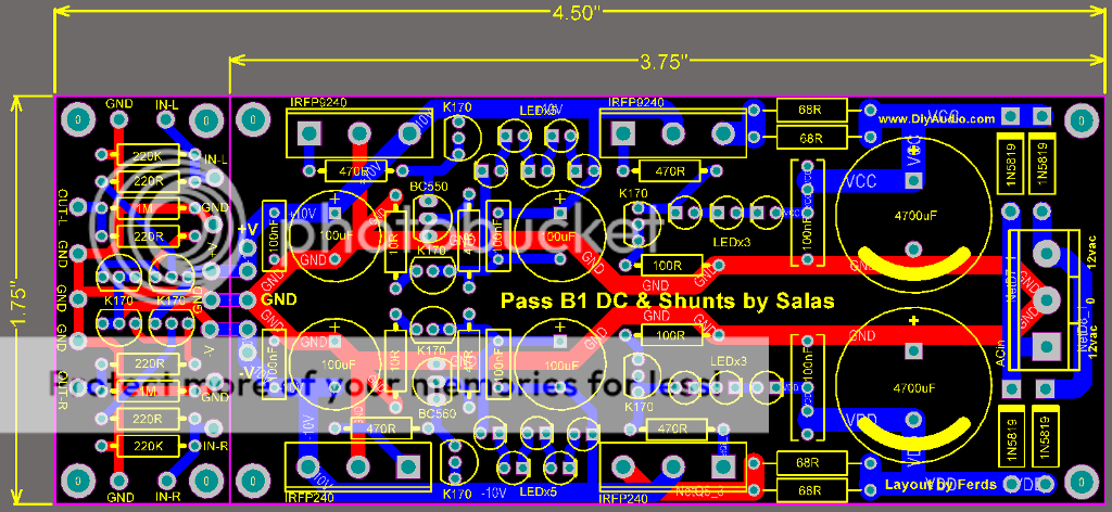
the measuring bridge (as drawn) ties into contaminated feed and return lines.
Identify the two feed connections that tap off the the output voltage and feed it to the top of the measuring bridge.
Identify the two return connections that tap off the ground/return voltage and feed it to the bottom of the measuring bridge.
These four connections must form the top and bottom of the measuring bridge at TWO points only. These two points should/must tap into the output not separated points spread out around the PCB.
It looks like no one was following the other shunt reg threads nor read Janneman/Jung regulators.
Can I hear someone/everyone saying "what? measuring bridge? Is this guy a crackpot? There's no measuring bridge in there."
The way it's drawn it's difficult to identify the measuring bridge that has an amplifier across the two midpoints and uses the error signal at these midpoints to send an amplified correction signal to the regulating FET.
Hello Ferds,
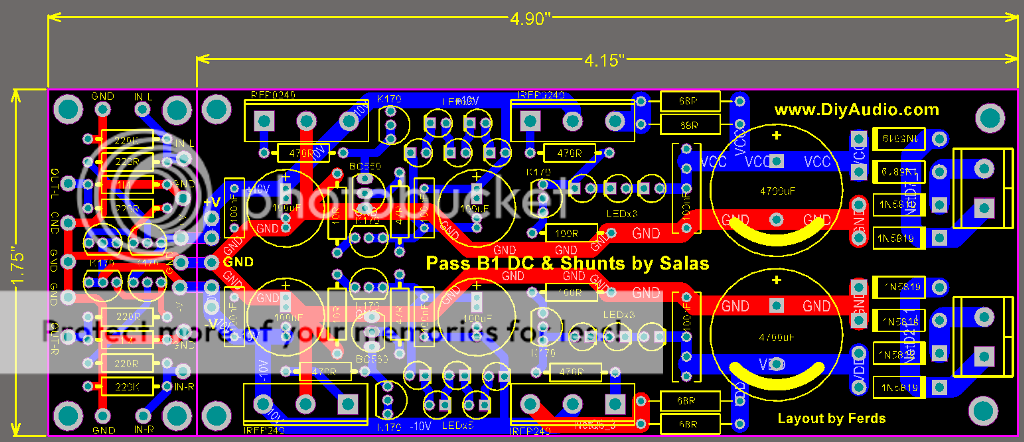
This update is an important step to versatility. It offers the possibility to make two bridges with two separate secundaries. By separating the common ground connection the AC-currents of positive and negative supply will not mix any more and this will contribute to a less noisy (=silent) supply. You only need a transformer with two separate secundaries. In case a transformer only has three wires in most cases you can separate the common ground connection when you carefully remove the isolation. I have done this often. It really is worth the effort when you want the most of it. It will only cost you four extra diodes.
The only thing that is needed on the pcb for those who want to use just one bridge are some extra pads to be able to make a shortcut with a wire between the two traces at the connection block and a wire from there to the two ground traces.
Ferds, could you check that please?
Compliments, Arjen.
av-trouvaille said:
Ferds, could you check that please?
ok, l'll try to work on it.. thanks
av-trouvaille said:The only thing that is needed on the pcb for those who want to use just one bridge are some extra pads to be able to make a shortcut with a wire between the two traces at the connection block and a wire from there to the two ground traces.
I tried to do your request but it seems i cant make it simple enough.. it just complicates things and can lead to error if the builder mistakenly jumper the wrong connections. sorry.. anyway its just additional 4 diodes...
thanks
Salas said:The two main filter caps and 0 of transformer must be closing together locally, and then continuing with a single trace to the star. In the redrawn pcb there is a gnd loop. Stick with #141
thanks for your reply salas.. how about with the 2 bridge diode? thanks
An externally hosted image should be here but it was not working when we last tested it.
xaudiox said:thanks for your reply salas.. how about with the 2 bridge diode?
The filter elements and bridges must close to a local star, and then connected to the signal star with a single trace. The way you have it, the recombining currents run to close at the signal star creating local contamination. We knew that Crt's board was buzz free because it was assembled and tested in two copies. The more ideas you incorporate to the new one the more it needs for a tested prototype before launch IMO.
The extra holes for the 100 uF caps would not hurt and they do not have negative side effects. Can you add them to the #141 PCB ? Apart from that maybe we can all mutually agree now that the power supply part leaves no desires ? It is a piece of art like it is !
About the buffer part: please consider to remove the input pads at the lower and upper side. They do not add anything IMO.
I know I always want too much but the orginaly planned muting relay ( as in the Salas schematic ) would be the icing on the cake ! Maybe two versions can be made ? A simple one and one with bells and whistles like muting relay, possibility for input and output caps for those that fear offset at either the output or the input. It is just an idea. The power supply building block is ready for both versions and can be copied to a second deluxe version.
Like others have commented before: I really appreciate your work and the time you put in this design, thanks again.
jean-paul said:I know I always want too much but the orginaly planned muting relay ( as in the Salas schematic ) would be the icing on the cake !
And what about a second relay for switching between two souces?
I know, I'm asking too much! A double cherry on the cake!
woodturner-fran said:I'll just throw it in here: If you wanted a muting relay then maybe it could be put on an extension to the existing board with a score line. That way you could use it or lose it as desired.
More space, so more money I know.. and more hassle
Fran
For a few $ more less plops and less risks on possible damage/annoying sounds. I like spartan gear but this is a luxury that adds satisfaction
If one wants to make a device DIY it only makes sense to make it better than ready built standard gear. DIY is more expensive anyway so why not go for the best ?
- Home
- Group Buys
- GB for DC coupled B1 buffer with shunt PSUs