I am interested in building a set of Buschhorn MKIIs. Can anyone give any insight as to how to scale the plan for a 11.5-12 cm driver like the Fostex FE126 as apposed to the 10 cm driver that the plan calls for? I have been trying to learn folded horn theory so I can modify the plan but it is taking time to find any good information and I am feeling frustrated about the situation. Any help would be appreciated! Thanks!
This fellow planted the FE126E into the Buschhorn MkII.
http://www.diyaudio.com/forums/showthread.php?s=&threadid=71466
It looks nice, but he did not comment on the sound.
On a side note, The Horn Shoppe has used a number of drivers (40-1197, FE103E, FE108ES and now FE126E) in their popular horn design. From their website, it looks like the swtich to the FE126E is done by adding some damping to the compression chamber.
Not quite a horn, but planet_10 has had some good results with the Fostex enclosure for the FE126E
http://www.diyaudio.com/forums/showthread.php?postid=831702#post831702
http://www.diyaudio.com/forums/showthread.php?postid=834672#post834672
I've also looked at building both the original Buschhorn and the MkII using FE126 drivers. Initially the original Buschhorn looked like the way to go because its size and foldings appear to be so similar to the Hornshoppe Horn.
Both the original and MKII need to have the compression chamber's height increased to physically fit the driver. After changing the heights I modelled both designs with various compression chamber geometries and volumes using MJ King's older BLH worksheet
The original Buschhorn seems to have too short a horn path length (I measured it to be approx. 62") and the Sthroat is also small in relation to the driver. The MkII also has a shorter path length that hampers its performance (I measured it to be approx. 76"). However after substantially decreasing the CC length and narrowing the area of the closed end the results were pretty good.
I also tried modelling Ron's A126E design with much better results. Unfortunately I couldn't get a good handle on the parameters of the CC and had to guess about actual lengths etc. Despite this the A126E design seems to work much better and appears go at least one more octave deep in bass. The original had a very ragged freq. resp. between 100 and 100 Hz with SPLs ranging from 70 dBs up to roughly 102 dBs. (I don't know how Ed from the HornShoppe does it!). Unfortunately I don't find ithe A126E to be as visually appealing as the Buschhorn or MkII and it looks like it would be much more difficult to build.
BTW I found that when modeling these designs that very small changes in the CC volume and geometry have a very large impact on the frequency response curves between 250 and 1000 Hz. No matter what I did I ended up with a ragged response (they are horns after all!) but I found it could be mitigated to some extent.
The parameters I came up with to model the Buschhorns with the FE126E were:
Original: Lhorn ~ 62" Sthroat = 0.265 Sd Smouth = 12.195 Sd
Mk II: Lhorn ~ 76" Sthroat = 0.4 Sd Smouth = 9.8 Sd
I couldn't come up with the expansion rate for either design so modeled all three types given in the King BLH worksheet (0=linear, 1=conical, 2=exponential). They both seemed to model the best with a linear expansion rate.
I'd be very interested in hearing from anyone else who has tried modeling and then building these designs. (Let me know if I screwed up!)
My thanks to you guys for your response! All of this is very good information! If anyone else has ideas, I am open to them as well. In addition, does anyone have any good links to horn theory? I know of all the mathcad papers and of the great work of some of the horn designers out there, however, I want basic theory, not pages of math. I can do the math when I fully understand why I am goind it. Thanks in advance!
Tom "Peregrinari" Petz
Tom "Peregrinari" Petz
I'm a bit light on horn theory, but Dave (Planet 10) is reportedly working on a 126E horn with Ron from the Full Range Driver Forum. You might want to check out the ups and downs of modeling that went on in that forum post.
Kofi
Kofi
Hey nice i have done a bit of research on that project, too! My first starting point was to build horns 'like' the hornshoppe ones. I had a discussion with Mr. Buschhorn himself on the design, it seems the folding is "similar" to his MK1, but with a bigger compression chamber. He suggested not to build a horn from the Mk1 design because of some design flaws, he recommended the Mk2 Buschhorn.
Another member of the forum had actually calculated the whole thing and recommended to increase the width of the MK2 from 16 to 20cm and then put the FE126E in it.
I haven't really come any further since i have something else in mind now (Ripole sub with satellite horns), because i want to give the fullranges a little rest from low frequencies.
Anyway, i would like to know where this leads you.
Good Luck!
Nils
Widening the MKII is a good idea that will increase both the throat and the mouth area. However the plans that I have from the Planet10 website (http://www.planet10-hifi.com/boxes.html) show the width as 13.5 cm not 16 cm (?). Increasing the width to 20 cm should move the mouth size to about 11.2 Sd -- an improvement but I suspect probably not far enough.
The FE126 will still be a tight fit vertically (less than 15 mm to play with).
The FE126 will still be a tight fit vertically (less than 15 mm to play with).
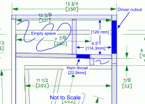
Just did some modeling of the FE126 in a MKII using King's MathCad worksheets (www.quarter-wave.com). I started with the 20 cm width and then tried 25 cm. Next I modified the CC by closing up the throat end and putting the throat at the back of the CC that shortened to 4.5". (The height of the CC must now be increased to fit the FE126). Further I adjusted the driver end and the throat end so that they both have an area of 1.8 x Sd. For the FE126 that's 65 cm2 x 1.8 = 117 cm2.
So what did this achieve?!:
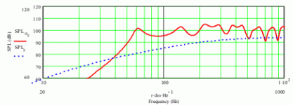
The performance of the original modeled with a straight expansion attached.
So what did this achieve?!:
The performance of the original modeled with a straight expansion attached.
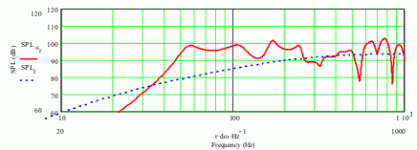
Now the results with the modifications attached (I think! - I'm still under moderation so I can't check immediately).
Modeling the horn as a straight, conical, or various hyperbolic-exponential expansion variants did not change the frequency ersponse much. The performance peak at approx. 60 Hz was raised to about 65 Hz and smoothened done a bit moving from a straight to conical to hyperbolic-exponential expansion.
The size of the mouth is still a limiting factor for the impulse response. Moving to a much better size of 18 Sd (or even better to 24 Sd) will improve this but not alter the freq response. Moving this high will require a change in the foldings as well (ie. abandon the MKII design).
Attachments
looks like the CC might be a bit too small, and almost exactly square? Intuition tells me you'll have some resonance issues.
Until you confirm by ear, you might want to allow for adjustment to the placement of that rear panel, as well as to apply it with some form of absorbtion ( acoustic foam or thick felt) . Also try a layer of thick felt to the back of the magnet.
These issues and your previously noted comment on the limitations resulting from the MKII's mouth size were the impetus for work by Dave on a design incorporating some of his own ideas.
The CC shape is up to the user and doesn't have to be box-shaped. Lengthening the CC without changing the area of the driver end and closed end increases the volume of the CC and can result in much more ragged (modeled) response. Increase the CC length to 6.5" here can be done by decreasing the areas from 1.8 Sd to 1.2 Sd. Further increasing the length of the CC here would require the area of the front and back of the CC to be unmanageably small (less than 1 Sd - smaller than the cone area of the driver).
As well in this particular design mod, increasing the CC will reduce the horn length and, because the horn is expanding it will also increase the throat area. I modeled the 4.5" to 6.5" CC change (with areas at the end moving from 1.8 Sd down to 1.2 Sd). Predictably the decrease in horn length slightly reduces the bass extension but surprisingly also starts to force a frequency rise from about 600 Hz to 900 Hz - probably not a good thing. Also the magnitude of the impulse response started to drop.
I agree that a layer of felt on the back of the driver would like benefit the sound however the addition of any amount of stuffing on the CC walls (felt, fibreglass, etc) seriously degrades the modeled SPL and impulse response. If reflections are a concern, curve the top of the CC and otherwise change the rear panel.
I recognize the modeling the speaker only gets you into the ballpark and you'll need to listen and fine tune the parameters as you go -- you just want to be in the right ball park.
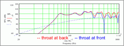
Just now I was thinking about the CC length increase and comments in (I think) the FullrangeDriver forum about Ron's A126. According to Ron the shortened CC modeled better but some users found an increased CC sounded better. Ultimately Ron was convinced to lenghten the CC and add a baffle. However Ron's design has the throat at the front of the CC (by the driver) not at the back. I think that's what's causing most of the problems heard and not the CC length -- I just can't get a horn with this throat positioning to model well. The location of the throat in the CC in the final modification of the A126 also moved the relative position of the throat towards the back of the CC.
chrisb - I'm intrigued with your remarks
chrisb - I'm intrigued with your remarks
-- Is this the "frugelhorn"? When are we going to hear more about this?These issues and your previously noted comment on the limitations resulting from the MKII's mouth size were the impetus for work by Dave on a design incorporating some of his own ideas.
holdent said:Just now I was thinking about the CC length increase and comments in (I think) the FullrangeDriver forum about Ron's A126. According to Ron the shortened CC modeled better but some users found an increased CC sounded better. Ultimately Ron was convinced to lenghten the CC and add a baffle. However Ron's design has the throat at the front of the CC (by the driver) not at the back. I think that's what's causing most of the problems heard and not the CC length -- I just can't get a horn with this throat positioning to model well. The location of the throat in the CC in the final modification of the A126 also moved the relative position of the throat towards the back of the CC.
chrisb - I'm intrigued with your remarks -- Is this the "frugelhorn"? When are we going to hear more about this?
Yes, this refers to the Frugal Horn - I've been gently prodding Dave to publish his concept. He's hesitating until after we get a prototype running, which could be a couple of weeks yet.
I built a pair of Ron's A126 Horns per the original plans, then modified the compression chamber both by increasing the volume and adding some diffractive and absortive materials.
As you alluded in your post #14, I'm quite aware that the math predictions and actual measurements don't always relate to what is heard, and have been known to say so, ( less than diplomatically.)
Your comments and graphs on the primacy of position of the throat in relation to the CC over it's shape are interesting - both the Hornshoppe and it's inspiration the BH MKI have the throat at the back of the rectangular CC. While lacking in lowest bottom octave, they both have far less of the coloration that I've referred to as "closed in" than I heard in the original A126, or for that matter the Buschorn MKII, or Fostex FE103BLH.
There's an interesting experiment for someone with a bit more time on their hands (and material to burn) than I currently have: build and actually audition two otherwise identical horns with the CC shifted to alter the throat location.
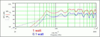
I just took another look at your graphs, FWIW, would modelling at a lower SPL, (say 90dB) have any affect on the degree of ripple? I get my hearing tested at work every year, and even though age and working environment have taken it's toll, my average listening is at the lowest volume since I used to leave the FM radio on all night long when I was a kid.
chrisb - The freq response curve stays the same but at lower levels (see attachment). Your hearing is not linear though (hence the addition of loudness buttons on receivers) so it will sound different. Another contributer to a different (better) sound will be the lower levels of IM distortion.
The FE126 driver is rated by Fostex to have a continuous power rating of 15 watts. However in practice the design of the horn will limit the power handling to lower levels by how well it controls the driver excursion for low frequencies (you can't exceed the Xmax of the FE126 at 0.35mm). In the modded MKII design 2 watts of power will exceed the Xmax for frequencies below about 25Hz. At 4 watts of power (ave. SPL level approx. 108 db) you'll exceed the Xmax for freqs lower than 40 Hz. Higher power levels can be achieved with much larger horn.
I should mention again that I've modeled this design using MJ King's excellent MathCad worksheets (www.quarter-wave.com). This is truly a great product.
Attachments
I had to download all of the drawings of the A126 at FullrangeDriver.com to get the required dimensions (look in the gallery). If I recall correctly there were several pieces I had to derive the measurements for (the angled pieces on the top at the back of the horn).
I haven't seen a cut sheet for this design yet.
I haven't seen a cut sheet for this design yet.
- Status
- This old topic is closed. If you want to reopen this topic, contact a moderator using the "Report Post" button.
- Home
- Loudspeakers
- Full Range
- Building Buschhorn MKII for 12 CM driver
