Bi-pole design
I guess I have been programed by the mass market designs to find the narrow cabinet more apealing. I recall a design that GM did for Pea using the JS92 that I liked. I think it would be possible to take the folded ML design put it on a psuedo stand with a down firing port and a slant front and I would be very happy.
Other comments:
The brace in between the two drivers needs to be just right and firmly anchored to both drivers. The mounting screws for the drivers must be bolts rather than screws if the brace is not just right. Harmonic and construction forces will challenge the integrity of the mounting screws. for visible ports I prefer slots with roled edges they seem more graceful to me.
Another thought:
I was reviewing some of the design work That MJK did with the Fe164. When he folded the TQWP it developed a ripple in the mid frequency range. One of our earlier designs has the fold point just below and behind the driver with the fold going side to side. This results in a wider front baffle, yet it appears to charge both sides of the line equally. With the fold going front to back I think it might be important to ensure the line gets charge equally. I am not sure how this can be evaluated?
Any thoughts?
SCD said:Another thought:
I was reviewing some of the design work That MJK did with the Fe164. When he folded the TQWP it developed a ripple in the mid frequency range.
That's surprising. All the statements I've read concerning folding pipes say that there are no detrimental effects.
 Did I miss something?
Timn8ter said:Minor variances in the length of the coupling dowel (-1mm) might be dealt with by placing a small amount of Duct Seal on the magnet backs where the dowel is placed. Does this seem an acceptable method?
That is similar to what NAIM is doing... so far the distances i've had to deal with can be covered with a sheet of paper (in fixed brace subs) or with the hot glue i use to loosely attach the dowel to the back of the magnet.
dave
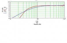
Maybe I read it a little too fast but I think the diagram on page 11, 12 shows a ripple. I am not as up on the theory as you guys I just threw the idea out there. I may be off the mark and it may not be an issue.
Firmly coupling the drivers is important. I have some ideas that I plan on trying. I will share once I get them a little more refined.
Firmly coupling the drivers is important. I have some ideas that I plan on trying. I will share once I get them a little more refined.
Hot glue was I what I was thinking as well.
The other idea was threaded rods at the mounting points. I was thinking about hexagon rod that was cut to length tapped and threaded. This may be over kill for this driver yet it is the one that is needed for the Push push bass drivers.
The other idea was threaded rods at the mounting points. I was thinking about hexagon rod that was cut to length tapped and threaded. This may be over kill for this driver yet it is the one that is needed for the Push push bass drivers.
Timn8ter said:That's surprising. All the statements I've read concerning folding pipes say that there are no detrimental effects.
Depends how well you fold it... in my fold the drivers are still appearing the same offset from the end of the line... in your fold they have different offsets (not necessarily a bad thing, just another detail the models don't handle)
dave
SCD said:The other idea was threaded rods at the mounting points. I was thinking about hexagon rod that was cut to length tapped and threaded. This may be over kill for this driver yet it is the one that is needed for the Push push bass drivers.
Similar to this?
An externally hosted image should be here but it was not working when we last tested it.
be nice if drivers all started coming such that you could put a big bolt or screw thru thru th epole piece to secure them (and not have th magnet unintentionally pulled off)
dave
planet10 said:
Depends how well you fold it... in my fold the drivers are still appearing the same offset from the end of the line... in your fold they have different offsets (not necessarily a bad thing, just another detail the models don't handle)
dave
True, I was considering the acoustical center of the backwave but really don't know how that all works out inside the enclosure. My bipoles to date have not been folded. Should we consider something similar to my bipole 1197s? No fold yet still a reasonably sized enclosure. We could mount the drivers on the narrow side too I would think.
On my drivers, I used two pieces of wood that are slightly larger that the magnets and then routed out a hole for the magnet to seat into. Then cut the eyelets off of both ends of a turn buckle and threaded them into the two wood rounds. Just slip it between the drivers and tighten to the desired pressure. They cant slip or loosen and can be taken on and off easily.
amt
amt
amt said:On my drivers, I used two pieces of wood that are slightly larger that the magnets and then routed out a hole for the magnet to seat into. Then cut the eyelets off of both ends of a turn buckle and threaded them into the two wood rounds. Just slip it between the drivers and tighten to the desired pressure. They cant slip or loosen and can be taken on and off easily.
amt
This necessitates a removable panel somewhere on the cabinet and assumes no bracing interferes with your hands/tools getting to the bolt. It's a very good concept though.
After looking at the possibilities I'm looking back to my initial proposal for a bipole on a psuedo-stand. Depending on the preferred listening height that would make the stand 20" to 25" high.
Attachments
coupling concept
Good thoughts AMT:
The concern I have with just a one way coupler is that it transfers the energy to the mounting screws or even to the glue holding the magnet to the driver. Dave has shown a good drawing of the concept I was trying to present. This may be a bit of over kill for this project though.
I was also wondering if plugging up the vent in the pole of the magnet with a bolt will effect the performance of the driver, but that is a queston for another discussion.
Re: coupling concept
In the case of the drivers that inspired the above drawing, the hole in the pole-piece was designed specifically to put a bolt (or in his case a lag screw). This designer would never put a vented pole-piece in any of his designs -- he doesn't like the soup-can resooance they cause.
dave
SCD said:I was also wondering if plugging up the vent in the pole of the magnet with a bolt will effect the performance of the driver, but that is a queston for another discussion.
In the case of the drivers that inspired the above drawing, the hole in the pole-piece was designed specifically to put a bolt (or in his case a lag screw). This designer would never put a vented pole-piece in any of his designs -- he doesn't like the soup-can resooance they cause.
dave
I actually took the concept partially from Mr Linkwitz, who mounts his mid-drivers by the magnet and not the frame. I just added a squeeze to the equation rather than a firm grasp. And you are right about access. I use a removable top plate on my speakers so I can re-wire, add tweeters etc. Another option would be a wedge block that fits between the drives and a threaded rod would expand it (like a bicycle stem) The rod could terminate at the bottom of the cabinet where it cant be seen. And it could be tightened after the speaker is functional.
amt
amt
The selected driver is the Fostex FE127E.
There will be two designs:
1. Single driver w/BSC
2. Two driver bipole wired in series.
We have one straight pipe bipole design and two folded bipole designs.
We do not have a monopole design although it should just be a matter of reducing the size of one of the bipole designs.
It appears our next step shoud be to select one of the bipole designs unless someone has another one to offer for consideration.
Timn8ter said:2. Two driver bipole wired in series.
We should be more flexible than to mandate series or parallel connection
We do not have a monopole design although it should just be a matter of reducing the size of one of the bipole designs.
Many of the bipole designs can just be sliced in half to become monopoles.
dave
Originally posted by planet10
We should be more flexible than to mandate series or parallel connection
True. It makes for an interesting comparison.
Originally posted by planet10
Many of the bipole designs can just be sliced in half to become monopoles.
Exactly. Shall we select one of the proposals? Then we can move on to construction specific things such as bookshelf or psuedo-stand and driver coupling techniques.
x. onasis said:As a "common to many of us" reference speaker project, I'll definitely participate, but let me just say that my feeling from the other "reference" project, is that we didn't set our goals high enough to get wider involvement.
Timn8ter said:The selected driver is the Fostex FE127E.
There will be two designs:
1. Single driver w/BSC
2. Two driver bipole wired in series.
We have one straight pipe bipole design and two folded bipole designs.
We do not have a monopole design although it should just be a matter of reducing the size of one of the bipole designs.
It appears our next step shoud be to select one of the bipole designs unless someone has another one to offer for consideration.
I suggest that we take a step backwards for the moment. One thing we have not done is set performance goals.
I suggest that the performance of this reference project should exceed the performance of the Fostex reccomeded enclosure:
http://www.fostexinternational.com/docs/speaker_comp/pdf/recom_enclose/127e_enclrev.pdf
Having said that, I think the next step should be to model a single driver design that will better the preformance of the Fostex design.
Once that is in place, the bi-pole version should essentially be a matter of doubling the mono-pole design. We could also investigate series and parallel connections.
If we do the bi-pole design first, we have no relative benchmark to judge the performance of the design.
Anyway, just my 2 cents.
Gio.
- Home
- Loudspeakers
- Full Range
- diyAudio Full Range Reference Project