planet10 said:Tim,
If you were to put a rebate into the baffle to flush mount the front of the 127, out deep would it be?
dave
The frame itself is only 2mm plus the final thickness of whatever sealant is chosen. The underside of the frame is not flat (the edge is rolled over) so the sealant will not change the total thickness very much. Since I'm using rope caulk I would stay at 3mm or 1/8" in the States.

Anyway, how about this?
Internal dims of 23"H x 6.5"W x 10"D. Drivers mounted on the narrow side 20" from the bottom (internal). Internal baffle when viewed from the wide side begins at 6" down 5" from the back, tapers to 1" from the back. A 2" x 2" port at the bottom on the back. Image below from Martin King's MathCAD worksheet
Attachments
Timn8ter said:Gio
BL is not doubled when wiring in parallel. Also, because of the larger size of the cabinet LF begins rolling off prematurely.Modeling two drivers in Martin King's MathCAD worksheets
Hi Tim,
My model was in series. I have gone through the MKJ document and while the text does not mention anything about doubling Bl in series, the example on the last two pages does show Bl as double. In that regard, it is not clear if Bl should be double or not.
Also, how do you know that the LF begins rolling off prematurely? Is that shown on the graphs or is that experience? I like to play around with the MathCAD models, but initial sizing of the cabinets is what I struggle with the most.
Regards,
Gio.
gmilitano said:
Hi Tim,
My model was in series. I have gone through the MKJ document and while the text does not mention anything about doubling Bl in series, the example on the last two pages does show Bl as double. In that regard, it is not clear if Bl should be double or not.
Also, how do you know that the LF begins rolling off prematurely? Is that shown on the graphs or is that experience? I like to play around with the MathCAD models, but initial sizing of the cabinets is what I struggle with the most.
Regards,
Gio.
Yes, I see where you show Re as double, I'm sorry for missing that. Just to be crystal:
TS parameters for two FE127E wired in series:
Fs = 70.4
Re = 13 ohm
Lvc = 0
Bl = 8.28
Sd = 133cm^2
Vas = 19.8 liter
Qe = .50
Qm = 3.33
For parallel Re would be 3.25 ohm and BL would be 4.14.
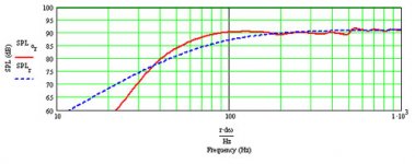
On page two of Martin's document the only time doubling BL is mentioned is when two drivers are wired in series. Compare my graph to your graph and you'll see where the LF begins to roll off. It may be personal preference but I like to keep LF up as long as possible before rolling off. Just MHO.
Timn8ter said:
Yes, I see where you show Re as double, I'm sorry for missing that. Just to be crystal:
For parallel Re would be 3.25 ohm and BL would be 4.14.
Compare my graph to your graph and you'll see where the LF begins to roll off. It may be personal preference but I like to keep LF up as long as possible before rolling off. Just MHO.
Great, sounds like I have the parameters all down, thanks for your help.
Perfect, I now understand what you mean by LF roll off, you mean the slope of the line (sorry, I speak better math than english)! Ok this makes sense.
Now, why I keep harping on the bass is becuase the series example of the 40-1197 in the MJK document. The 1197 has an Fs 0f 83 and a Qtd of .372 compared to the Fs of 70 and Qtd of .435 for the FE127E.
Despite that, the 1197 is getting about 62Hz at 0dB and 55Hz at -3dB, while we a more like 80Hz at 0dB and 60Hz at -3dB. Considering we have a bigger driver, with lower Fs and higher Q, I think we should be able to better the LF of the 1197 by 10Hz or more.
I was hoping to be able to get more low end out of these two drivers. Perhaps we should ask the question of how much bass we would like to see out of this project?
I would like to see (hear!) at least 50Hz at -3dB or better.
Anyway, lets hear what others think.
Gio.
While I think Martin King's MathCAD worksheet is a wonderful tool it is still a tool. Martin has told us that there are some things that are not reflected accurately in the modeling, one in particular being baffle step. The bump you see in the example graphs for the 1197 is an anomoly. What I see is that the FE127E is 50hz at 85db, which is lower than the 1197. Granted, it's not much but when you start driving for bass response beyond Fs*.707 you risk loss of cone control and from experience I can tell you the 127 will "slap" at moderate volume levels during heavy bass tracks and when not slapping will muddle the mid-range.
Great project guys.
Gio,
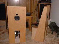
Trying to get too much LF out of the drivers will definately rob them of midrange clarity. Ive built 8 different speakers using the 1197 and an ob with a helper woofer was clearly the best way of keeping as much midrange magic as possible. Second best is the bipole arrangement which Ive used as HT for 4 years now. BTW, I find that parallelled drivers and the gain in efficiency adds much to the dynamics of the drivers. . My gainclones and Sonic Impact based amps have no problem with 4 ohm loads and the gain in output and "speed" is noticable to me. Below is my best effort at a 4". All dipole and done on the cheap. My current thoughts are of a bipole, backhorn design.
amt
Gio,
Trying to get too much LF out of the drivers will definately rob them of midrange clarity. Ive built 8 different speakers using the 1197 and an ob with a helper woofer was clearly the best way of keeping as much midrange magic as possible. Second best is the bipole arrangement which Ive used as HT for 4 years now. BTW, I find that parallelled drivers and the gain in efficiency adds much to the dynamics of the drivers. . My gainclones and Sonic Impact based amps have no problem with 4 ohm loads and the gain in output and "speed" is noticable to me. Below is my best effort at a 4". All dipole and done on the cheap. My current thoughts are of a bipole, backhorn design.
amt
Attachments
One might hope the term "elegant" would suggest more universal appeal.
(end of sarcasm)
Question: How important is the level placement of the opposing drivers in regard to BSC? IOW, Could the rear driver be placed slightly higher? This might necessitate a braced, rectangular board as a mechanical coupler for the drivers.
And as a related follow-up ... might the rear driver's TL be a simple L shape, placed over the top and rear of the of the single driver plan? This might provide for a cab still around 8" wide and 12" deep.
(end of sarcasm)Question: How important is the level placement of the opposing drivers in regard to BSC? IOW, Could the rear driver be placed slightly higher? This might necessitate a braced, rectangular board as a mechanical coupler for the drivers.
And as a related follow-up ... might the rear driver's TL be a simple L shape, placed over the top and rear of the of the single driver plan? This might provide for a cab still around 8" wide and 12" deep.
(my quote function ain't working at the moment)
"I can tell you the 127 will "slap" at moderate volume levels during heavy bass tracks and when not slapping will muddle the mid-range."
I keep thinking how Dave used to keep reminding us of the benefit of going active for bass, ie. "frees the mid up to do what it does best." (or in this case, the full ranger)
juggle2 said:One might hope the term "elegant" would suggest more universal appeal.
A term from my math days... nothing to do with visual appeal. But i did come up with one that was not your regular box -- the geometry is probably too extreme to work (which is why i held off posting it). The terminus would probably be best not as a tube, but built in as part of the box -- perhaps a development of the point. Flip it 180 degrees and you could hang them from the ceiling by the point.
Question: How important is the level placement of the opposing drivers in regard to BSC? IOW, Could the rear driver be placed slightly higher? This might necessitate a braced, rectangular board as a mechanical coupler for the drivers.
Won't affect BSC, but in a TL will much with the tuning developed by having a driver offset... the drivers need to appear to the line like they are in the same place.
dave
Attachments
planet10 said:a little creative paintwork, and no one would know its a speaker...
dave
Hmmmm....it's interesting what comes out of your mind at 2am Dave. Kinda like the eyeball on the US dollar bill. Illuminati?

(No, I still haven't read it.)
The curved top is interesting but time is a valuable quantity for me lately. I doubt I would build it. I do like the idea of a folded pipe though because the common version is quick and easy to build.
Timn8ter said:The curved top is interesting but...
The Flat-Top (tm) version:
internal reflectors are optional (2 possible drawn in green & magenta)
Port out the front, back, side, or bottom (as illustrated).
Next up the lated Tim suggestion. Supper 1st.
dave
Attachments
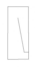
Timn8ter said:Internal dims of 23"H x 6.5"W x 10"D. Drivers mounted on the narrow side 20" from the bottom (internal). Internal baffle when viewed from the wide side begins at 6" down 5" from the back, tapers to 1" from the back. A 2" x 2" port at the bottom on the back
Like this?
dave
Attachments
The Flat-Top (tm) version:
...not "Prune Face", thankfully.
Like this?
 Oh yeah, I guess we decided it should have a down-firing port. Still could. I had the top of the line ending 4 inches up from the bottom of the cabinet allowing room for a rear firing port. This could easily accomodate a down-firing port also.
Attachments
Morning boys:
I foolishly went to bed last night and missed all the fun. Somewhere back in the discussion things turned to a stand mount for the bipole. Any reason we could not do the bipole as a free stander tower. Some designs I have seen put a pseudo stand together with a short cabinet. It uses a down firing port and a slant front. This could easily be mounted on a solid base. The space behind the slant can be loaded with either lead shot or baked sand.
I foolishly went to bed last night and missed all the fun. Somewhere back in the discussion things turned to a stand mount for the bipole. Any reason we could not do the bipole as a free stander tower. Some designs I have seen put a pseudo stand together with a short cabinet. It uses a down firing port and a slant front. This could easily be mounted on a solid base. The space behind the slant can be loaded with either lead shot or baked sand.
SCD said:Morning boys:
I foolishly went to bed last night and missed all the fun. Somewhere back in the discussion things turned to a stand mount for the bipole. Any reason we could not do the bipole as a free stander tower. Some designs I have seen put a pseudo stand together with a short cabinet. It uses a down firing port and a slant front. This could easily be mounted on a solid base. The space behind the slant can be loaded with either lead shot or baked sand.
That was actually discussed earlier and is the reason for the down-firing ports in the drawings from Dave except for mine, however, it's easy enough to move the port to that position. Determining the output for the port in a psuedo-stand will be an interesting exercise. GM had described how to do that without turning it into a horn. I'll have to look around for that info. IIRC, he recommended having the port tube exit into a slot port. My bipole FE103E uses a slant front which interestingly enough sounds better when it's off the floor several inches.
- Home
- Loudspeakers
- Full Range
- diyAudio Full Range Reference Project