Thanks to all for playing! If we didn't share and show our results we wouldn't learn a thing, right? 😉
Thanks to all for playing! If we didn't share and show our results we wouldn't learn a thing, right? 😉
Agree its beautiful point here at domain, and reason if I ever get to Netherlands again can maybe have a listen to Rephase Rewire mkII version.
Agree its beautiful point here at domain, and reason if I ever get to Netherlands again can maybe have a listen to Rephase Rewire mkII version.
Hopefully plus subs! 😀
I didn't understand this at all, and asked my manager at the time what on earth was going on. He explained that when they are series wired, the individual drivers are not necessarily at the exact same position...
It would seem that when wiring more than a couple of drivers in series and sharing the same airspace you need to take the entire electrical model of a driver into consideration (if you're pursuing perfection)! We are all assuming that the drivers are purely resistive and inductive. If that were the case then the entire series string of drivers can be modeled as one inductor and resistor, meaning each voice coil would have the same current, and thus the same cone movement (assuming everything else is the same).
Unfortunately the voice coil is usually more than one layer of windings which creates lots of distributed capacitance not only between adjacent windings in the same layer but also between adjacent windings in adjacent layers. That makes the actual model much more complicated.
Last edited:
Owen, did the sim at Blackberry assume identical drivers?
Because I can see how slight tolerances could cause the problems you saw at Paradigm. We know these drivers differ in Mms, Re, Fs, sensitivity... A volume manufacturer could match, but that's not going to work for some who buys a few dozen from PE.
Who knows X well enough to see what Akabak thinks?
Years ago, I made a model of the two towers, before there was a two towers thread. I think I varied the TS parameters of each driver a bit even. I will dig it up and see what happens with 5 series vs parallel. From a standpoint of phase, I can see what this would be. The pressure nodes inside a rear chamber may not be uniform and this affect cone position. If one is in different position, there is a chance that the pressure phase and electrical phase are 180 apart and this will result in runaway oscillation and higher displacement on certain drivers. In parallel wiring this would be less of an effect. So if there were 5 sub chambers ea should be parallel and the 5 separate chambers should be in series.
Your example of six identical drivers in a single enclosure (be it hexagon or linear, whatever) brings up an interesting possibility: All drivers, whether connected in series or parallel, would produce a pressure wave capable of shredding an idle driver. 5 drivers in series, in parallel, or separately amped, might produce a pressure wave capable of shredding a passive radiator or disconnected driver of the same spec.Hi Wesayso,
Amazing work here! I'm very glad you took the time to run this as I just didn't have the time to run the sims and to get such a concise summary together.
Also, to be clear, I'm definitely not the smartest one here... I've just been lucky enough to run into these things throughout my career, and to learn from people far smarter than I could ever hope to be 😉
In addition to this, your arrays kick my array's butt!
I also didn't want to rain on fluid's parade as I know how much work it is to get the arrays wired up, and he hit a pretty big milestone getting both arrays up and running.
Some background on this:
My first job out of school was at Paradigm and the first project I worked on was the 3kW class D amplifier used in the "Sub 1" and "Sub 2" products. A quick google search will show you what these look like, but they are basically hexagons where 6 individual drivers share a common volume, and are all driven by a single amplifier (Sub 2) and two amplifiers (Sub 1).
The prototype version of this product used a series arrangement for the drivers (I think it was 2 ohm drivers wired 6 in series for a 12 ohm final impedance to get maximum output from the amplifier). This version literally tore itself apart, completely snapping a cone in half on one of the drivers. I didn't understand this at all, and asked my manager at the time what on earth was going on. He explained that when they are series wired, the individual drivers are not necessarily at the exact same position, and if one gets out of phase enough with the others, the remaining 5 drivers will destroy it. In addition to the potential for damage, it also has a huge negative impact on output for obvious reasons. In the end, the drivers were changed to be 70 ohms and all wired in parallel. This arrangement worked perfectly, and is what is shipping today. At the time I didn't really understand it, and just wrote it off as "oh, that's cool.. don't wire drivers sharing a common volume in series". I was more of an amplifier guy than a speaker guy back then 😉
Later in life, at Blackberry, when I was spending more time doing microacoustics, I asked our local physics/audio guru guy if he had ever heard of this, and he said it made no sense... both series and parallel wiring should not make a difference. I insisted that it did, and he was interested enough that he built an entire model (at the time in our custom BlackBerry acoustics simulation tool) and sure enough, the cone position of parallel wired transducers remained very close, where the cone positions of the series wired devices were all over the place.
To be honest, I still don't fully understand precisely what the mechanism is here, but I think the answer would be obvious if you used a Klippel to plot cone position, terminal voltage, and current as a sine wave on a scope while sweeping frequency. Below resonance cone position should be proportional to voltage, at resonance I don't really know, and above resonance things should go back to voltage proportional until breakup occurs, then all bets are off. I get the feeling that in the above scenario, voltage will track much more closely to cone position than current will throughout the entire frequency range, but in particular, at low frequencies and at resonance where it matters most when several drivers are sharing the same volume.
If there is any way to plot excursion of the 5 drivers while accounting for the shared volume, that would be the best way to show the impact of this.
At the end of the day, this is definitely not a minor detail! You will get significant benefits from only running parallel drivers in a shared sealed volume. My apologies to fluid for being the bearer of bad news 🙁
Regards,
Owen
Placing a short across one of six drivers in a series circuit would effectively remove it, as would an open circuit on one of six parallel drivers. Near the tuning frequency created by the enclosure and the disconnected passive radiator, the PR would enhance the output. Below the tuning frequency, the PR would fight the output, moving in when the others move out.
If the other drivers in the system are already approaching Xmech, the relative magnitude of the passive radiator would be up to 5x the magnitude of travel compared to the active radiators. So in any sealed enclosure with multiple drivers, series or parallel, should an active driver become passive, the cumulative effects of the other drivers might destroy it.
This is unlikely to result in damage with only two drivers, for instance a stereo boombox or MTM enclosure, because even if the driver cones added, subtracted, or one acted as a passive radiator (boombox with shared enclosure and only one driver being driven), the movement of a single rogue driver would never exceed the others.
So the more drivers we add to a single enclosure, the more likely one driver will become overpowered. In the case of the six woofers in a single box, just placing your hand upon the cone to impede it's movement may be enough to push it out of compliance, and once out of compliance, the single out of phase driver will be playing tug-of-war with the rest of the group.
Even if non-conformant behavior of any one driver did not cause enough travel to destroy it, I imagine the effects would definitely be audible even at lower volumes. Constructive and destructive interference or oscillations between drivers within the resonant chamber could be muted by the placing of walls between the driver chambers.
In a perfect system, the sound pressure on each barrier of identical sub-enclosures would be equal, so little damping would be required. 1/4" MDF barriers between otherwise identical cells would be enough to prevent driver behavior. In mechanical engineering, such an element is known as a "zero force member" for instance lightweight beams interlocking support struts of a bridge prevent resonances or buckling within the bridge structure, so a thin barrier would prevent drivers in adjacent cells from interacting with each other. The outer walls of the structure would still need to be 3/4" minimum to prevent resonances between the internal enclosure and the outside, as well as provide structural support, then the thin walls in each cell nullify inter-driver modulation.
Of course, creating cells out of thin material would require removing at least one panel of the existing structure, assuming it isn't already permanently glued together. But celling off all drivers would be the only way to ensure the entire array would behave, with each driver being it's own sealed enclosure.

Akabak Sim of 5 driver Array with Common Chamber
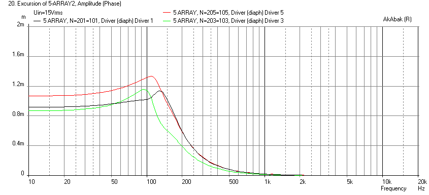
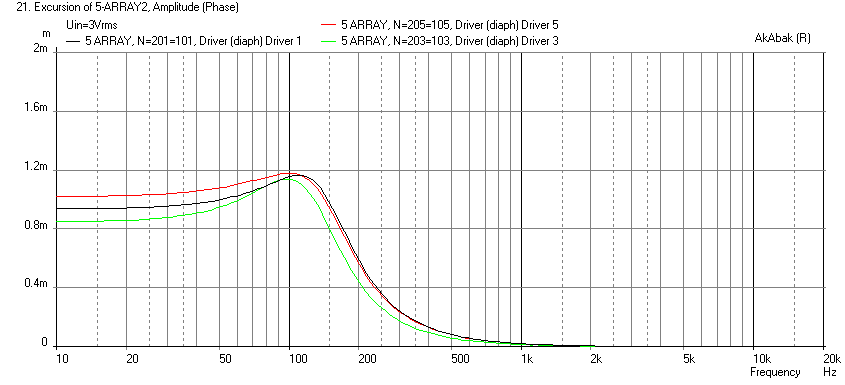
I made a model of a 5 driver array with TC9FD's packed as close together as possible vertically. The rear chamber has dimensions of 4.25in W x 12in D x 21.36in H for a 17.84 liter rear chamber or 3.57 liters per driver - about right for TC9FD as a minimum. The rear chamber was modeled as 6 "Duct" segments with the driver rear cones located at the duct boundaries. I wired the arrays in series in 1 case and in parallel in the other case. In order to drive them to equivalent powers, I used 15v rms for the series case and 3v rms for the parallel case. I also have the ability to change or eliminate stuffing in the rear chamber (this basically adds resistance to the airflow in the rear chamber. At first there were only very small observable differences in the cone displacements between the two cases. However, when I added small (typical) variations in the T/S parameters of the drivers, the differences magnified themselves when in series wiring.
Here are the different TS params that I used (I hand adjusted them to give scatter):
Here is the cone displacement for SERIES wired:
Here is cone displacement for PARALLEL wired:
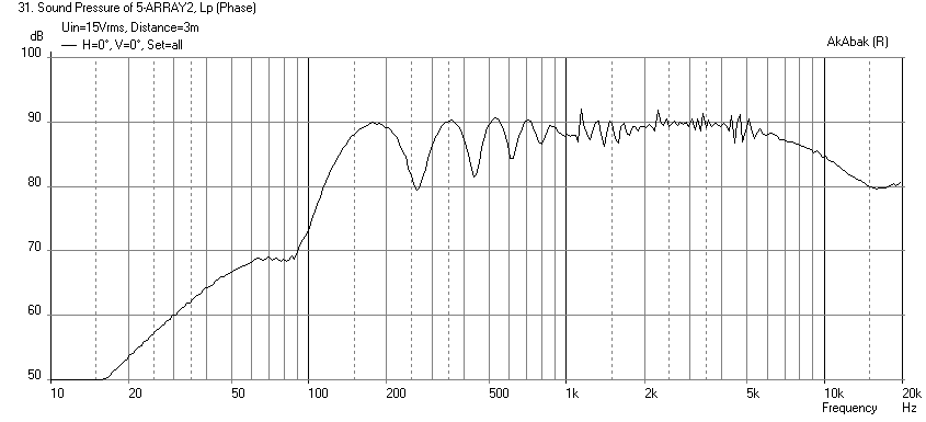
Here is the SPL produced 3m away with the speaker centerline (driver 3) at 40in above the floor, and no back wall reflections, for SERIES:
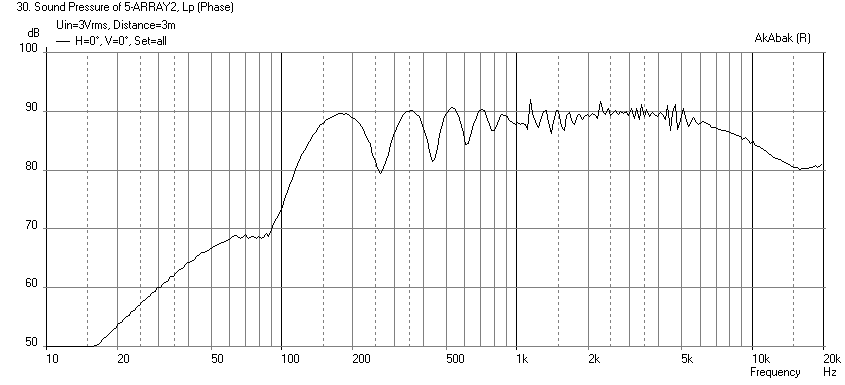
Same for PARALLEL (as you can see it doesn't affect the frequency response much):
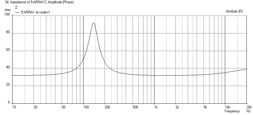
Here is Impedance for SERIES with stuffing:
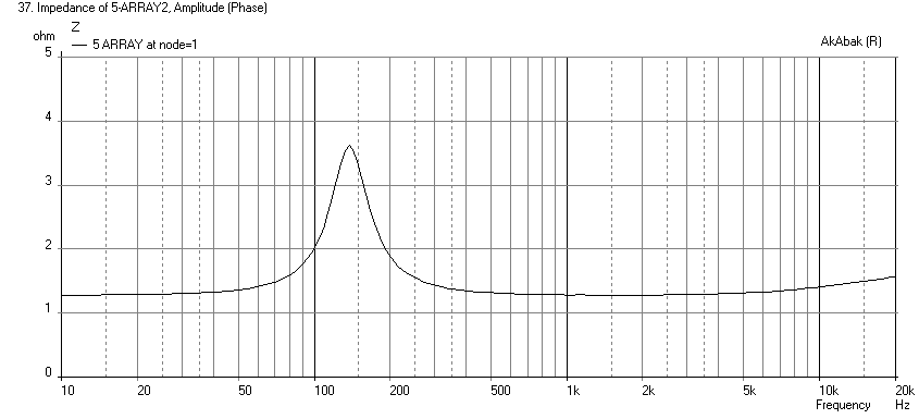
Here is Impedance for PARALLEL with stuffing:
Here is Impedance for SERIES when stuffing is removed (see the little blips show up now):

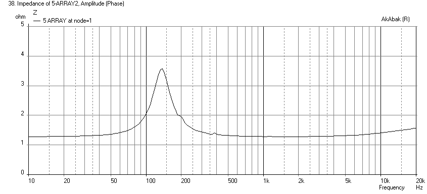
Here is Impedance for PARALLEL when stuffing is removed:
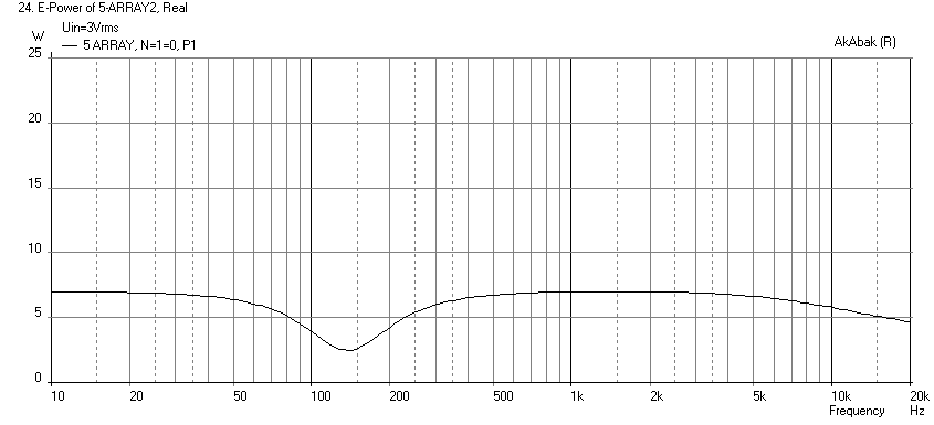
Here is electrical power for both cases to show that the drive power is the same (Series):
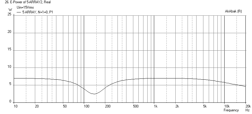
Electrical power for Parallel:
So, it does indeed look like series wiring produces some "chattering" between the drivers. You may not hear anything at low powers, but I think it may be more significant for higher powers and deeper cone excursions. It matters more when drivers are not matched.
An analogous situation with audio power amps using multiple output devices also happens. When parallel output transistors or MOSFETs are used, low impedance (circa 0.22ohms to 0.47ohms) power resistors are often used between each transistors' output and the common summing point output in order to allow self-load balancing because the transistors have different characteristics. Distortion is increased when they are not well matched. Without the load balancing resistors, some transistors can damage the others since they "fight". So damping or stuffing in the rear chamber really helps to alleviate this.
I made a model of a 5 driver array with TC9FD's packed as close together as possible vertically. The rear chamber has dimensions of 4.25in W x 12in D x 21.36in H for a 17.84 liter rear chamber or 3.57 liters per driver - about right for TC9FD as a minimum. The rear chamber was modeled as 6 "Duct" segments with the driver rear cones located at the duct boundaries. I wired the arrays in series in 1 case and in parallel in the other case. In order to drive them to equivalent powers, I used 15v rms for the series case and 3v rms for the parallel case. I also have the ability to change or eliminate stuffing in the rear chamber (this basically adds resistance to the airflow in the rear chamber. At first there were only very small observable differences in the cone displacements between the two cases. However, when I added small (typical) variations in the T/S parameters of the drivers, the differences magnified themselves when in series wiring.
Here are the different TS params that I used (I hand adjusted them to give scatter):
Code:
Def_Driver  'TC9FD-1'
  SD=36.3cm2   |Piston
  fs=125Hz
  Mms=2.43g
  Qms=2.70
  Qes=1.33
  Re=6.3ohm
  Le=0.05mH
  Bl=3.01Tm
  Vas=1.13L

  Def_Driver  'TC9FD-2'
  SD=36.3cm2   |Piston
  fs=120Hz
  Mms=2.38g
  Qms=2.80
  Qes=1.36
  Re=6.2ohm
  Le=0.055mH
  Bl=3.1Tm
  Vas=1.14L

  Def_Driver  'TC9FD-3'
  SD=36.3cm2   |Piston
  fs=110Hz
  Mms=2.35g
  Qms=2.60
  Qes=1.29
  Re=6.5ohm
  Le=0.045mH
  Bl=2.90Tm
  Vas=1.12L

  Def_Driver  'TC9FD-4'
  SD=36.3cm2   |Piston
  fs=127Hz
  Mms=2.53g
  Qms=2.75
  Qes=1.39
  Re=6.35ohm
  Le=0.052mH
  Bl=3.3Tm
  Vas=1.17L

  Def_Driver  'TC9FD-5'
  SD=36.3cm2   |Piston
  fs=120Hz
  Mms=2.49g
  Qms=2.78
  Qes=1.39
  Re=6.6ohm
  Le=0.066mH
  Bl=3.2Tm
  Vas=1.21L
Here is the cone displacement for SERIES wired:
Here is cone displacement for PARALLEL wired:
Here is the SPL produced 3m away with the speaker centerline (driver 3) at 40in above the floor, and no back wall reflections, for SERIES:
Same for PARALLEL (as you can see it doesn't affect the frequency response much):
Here is Impedance for SERIES with stuffing:
Here is Impedance for PARALLEL with stuffing:
Here is Impedance for SERIES when stuffing is removed (see the little blips show up now):
Here is Impedance for PARALLEL when stuffing is removed:
Here is electrical power for both cases to show that the drive power is the same (Series):
Electrical power for Parallel:
So, it does indeed look like series wiring produces some "chattering" between the drivers. You may not hear anything at low powers, but I think it may be more significant for higher powers and deeper cone excursions. It matters more when drivers are not matched.
An analogous situation with audio power amps using multiple output devices also happens. When parallel output transistors or MOSFETs are used, low impedance (circa 0.22ohms to 0.47ohms) power resistors are often used between each transistors' output and the common summing point output in order to allow self-load balancing because the transistors have different characteristics. Distortion is increased when they are not well matched. Without the load balancing resistors, some transistors can damage the others since they "fight". So damping or stuffing in the rear chamber really helps to alleviate this.
Attachments
-
 Array5-Series-Displ.PNG27.6 KB · Views: 2,475
 -
 Array5-Parallel-Elect-Power.PNG24.7 KB · Views: 1,822
 -
 Array5-Series-Elect-Power.PNG24.7 KB · Views: 1,835
 -
 Array5-Parallel-Impedance-No-Stuffing.PNG25.3 KB · Views: 1,843
 -
 Array5-Series-Impedance-No-Stuffing.PNG25.9 KB · Views: 1,864
 -
 Array5-Parallel-Impedance.PNG25.3 KB · Views: 1,868
 -
 Array5-Series-Impedance.PNG25.7 KB · Views: 1,912
 -
 Array5-Parallel-FR.PNG27 KB · Views: 1,911
 -
 Array5-Series-FR.PNG26.8 KB · Views: 1,935
 -
 Array5-Parallel-Displ.PNG27.3 KB · Views: 2,453
Last edited:
Wow lots of posts overnight (for me) so let me see if I can respond.
The limitation on these simulations is that they are using free air measurements to show variations but they don't take into account box interaction so it is not a complete model, useful none the less.
Hmm, seen as we don't understand it and can't really explain it what are the significant benefits? What is the bad news?
Seems like a bit of a paradox in that I haven't heard yours and you haven't heard mine so how do we know if it makes any difference to the way it performs as a speaker?
Thats an interesting simulation. There is no doubt that in summing terms more parallel connections gives better results. As I have 50 real world free air impedance measurements it would be interesting to see if there are any differences noted in the order in which they are connected. I can supply them to wesayso or Byrtt if they would like to play, at this point I still need to fully finish my array's.@stardust4ever well I don't know about that...
I had begged BYRTT to supply me his X-Sim simulation so I could check it on a driver level to find out what is happening.
(Yes I am that crazy that I would consider doing a complete re-wire 😀)
The limitation on these simulations is that they are using free air measurements to show variations but they don't take into account box interaction so it is not a complete model, useful none the less.
No problem 😉Thanks to BYRTT for supplying the sims, to OPC for opening my eyes, to bwaslo for the amazing X-Sim program and fluid for the hospitality on this thread 🙂.
Thanks for trying to spare my feelings, don't worry I'm not that fragile 😉 It's really great that you are posting again as you have used one of these types of speaker for a long time so your experience is valuable.I also didn't want to rain on fluid's parade as I know how much work it is to get the arrays wired up, and he hit a pretty big milestone getting both arrays up and running.
This example shows the need to consider this phenomenon but the array here is a very different setup which needs to be remembered. There are no cones being ripped apart here and the motion at high excursion does not seem any different to the eye for whatever that is worth.This version literally tore itself apart, completely snapping a cone in half on one of the drivers. I didn't understand this at all, and asked my manager at the time what on earth was going on. He explained that when they are series wired, the individual drivers are not necessarily at the exact same position, and if one gets out of phase enough with the others, the remaining 5 drivers will destroy it. In addition to the potential for damage, it also has a huge negative impact on output for obvious reasons.
That would be nice to do but unless a major manufacturer wants to build one of these (which I doubt, too much work) then I think speculation will rule the day.To be honest, I still don't fully understand precisely what the mechanism is here, but I think the answer would be obvious if you used a Klippel to plot cone position, terminal voltage, and current as a sine wave on a scope while sweeping frequency. Below resonance cone position should be proportional to voltage, at resonance I don't really know, and above resonance things should go back to voltage proportional until breakup occurs, then all bets are off. I get the feeling that in the above scenario, voltage will track much more closely to cone position than current will throughout the entire frequency range, but in particular, at low frequencies and at resonance where it matters most when several drivers are sharing the same volume.
I agree this would be helpful, not sure how to do it though.If there is any way to plot excursion of the 5 drivers while accounting for the shared volume, that would be the best way to show the impact of this.
I'm not sure that there is enough data to make that statement about my array. The way I have built it actually runs counter to my original intention but I really can't do anything about that now. If nothing else this cabinet will highlight whatever those issues are when applied to these drivers in this configuration, so lets wait and see what it measures and sounds like when EQ'd properly.At the end of the day, this is definitely not a minor detail!
You will get significant benefits from only running parallel drivers in a shared sealed volume. My apologies to fluid for being the bearer of bad news 🙁
Hmm, seen as we don't understand it and can't really explain it what are the significant benefits? What is the bad news?
Seems like a bit of a paradox in that I haven't heard yours and you haven't heard mine so how do we know if it makes any difference to the way it performs as a speaker?
So true, which is part of what I have tried to do here. I also think seeing the actual outcome of this phenomenon in terms of standard speaker measurements will be useful learning too. How many people wrote off your array due to "comb filtering" and it being too big of a problem when in reality it doesn't ruin your enjoyment.Thanks to all for playing! If we didn't share and show our results we wouldn't learn a thing, right? 😉
Agree its beautiful point here at domain, and reason if I ever get to Netherlands again can maybe have a listen to Rephase Rewire mkII version.
I really hope I can get to hear Wesayso's towers after mine are finished.Hopefully plus subs! 😀
Agreed, the interaction between variables is quite significant.That makes the actual model much more complicated.
Seems like a good idea but not what I did so now we can see what effect it has 😉So if there were 5 sub chambers ea should be parallel and the 5 separate chambers should be in series.
So, it does indeed look like series wiring produces some "chattering" between the drivers. You may not hear anything at low powers, but I think it may be more significant for higher powers and deeper cone excursions. It matters more when drivers are not matched.
An analogous situation with audio power amps using multiple output devices also happens. When parallel output transistors or MOSFETs are used, low impedance (circa 0.22ohms to 0.47ohms) power resistors are often used between each transistors' output and the common summing point output in order to allow self-load balancing because the transistors have different characteristics. Distortion is increased when they are not well matched. Without the load balancing resistors, some transistors can damage the others since they "fight". So damping or stuffing in the rear chamber really helps to alleviate this.
Could you extend that model to have the 5 series/parallel connected versions to represent the same layout I have? The impedances are obviously completely different in a pure series vs parallel arrangement like you have there.
From my own impedance measurements it is clear that the more series drivers you have in the same volume the more unsettled the impedance plot is. It is also possible to sort the drivers into groups where the differences average out. The question still remains does this matter in practice and what is the penalty if it does. I have two almost identical towers except for the sorting of the drivers and the impedance plots they create. Measuring them separately should show some difference and it will be interesting to see where that difference comes from.
From X's simulation and some of the other comments it would seem that distortion may be the best place to look to see what is happening and that measurements of increased spl should show increased distortion over and above what would be expected.
Owen, are you able to take any distortion measurements of your setup at different spl's to allow a comparison of them to mine when I get to them?
I can run a simulation of series parallel but I can predict what will happen is the impedance plot will be a blended average of the pure parallel and pure series with a nominal Re value of circa 7ohms or so. It's a lot of code to make this happen and I am not sure if you will learn anything new.
I am not sure if you wiring harness is now inaccessible or you don't want to rewire it. Series wiring is very simple if you use Faston crimp connectors - just daisy chain top to bottom +ve to -ve of successive drivers and take two ends as output. The parallel all the leads from each chamber.
Frankly I don't think it will be a big deal to run 5 in series if you use a decent amount of stuffing in the chambers. The volume displacement of one driver is not going to be killed by 4 other drivers. These are, after all, just little 3.5in toy drivers when compared to big 12in or 15in pro audio woofer in terms of displacement and power.
I suspect you won't hear anything different - a little fuzz on impedance sweep never hurt anyone. 🙂
What's important is that it doesn't generate excessive third or odd order distortion relative to a correctly wired one.
It wasn't for the overall impedance more to see if the differences between excursions of the drivers changes in the series parallel arrangement. I understand if it is too much hassle 🙂I can run a simulation of series parallel but I can predict what will happen is the impedance plot will be a blended average of the pure parallel and pure series with a nominal Re value of circa 7ohms or so. It's a lot of code to make this happen and I am not sure if you will learn anything new.
It is not inaccessible unless you count the fact that I would have to remove all the drivers to get at it. The issue is that it is glued and routed through the separate cabinets so I can't just add 4 more sets of parallel connections. It's a lot of extra wire to do a line like this in parallel series like Owen. Wesayso could do it to his as his front baffle is removable mine isn't as it is glued down and covered in fabric and felt.I am not sure if you wiring harness is now inaccessible or you don't want to rewire it. Series wiring is very simple if you use Faston crimp connectors - just daisy chain top to bottom +ve to -ve of successive drivers and take two ends as output. The parallel all the leads from each chamber.
I think you are right my cabinet is pretty well stuffed and I have run them pretty hard with 10Hz tones. There was no runaway oscillation or driver destruction. If it presents an issue it will be more subtle than that and will probably be a rise in distortion.Frankly I don't think it will be a big deal to run 5 in series if you use a decent amount of stuffing in the chambers. The volume displacement of one driver is not going to be killed by 4 other drivers. These are, after all, just little 3.5in toy drivers when compared to big 12in or 15in pro audio woofer in terms of displacement and power.
True, although I would like it to look nice if I can get it, but I'll take sounding good in preference.I suspect you won't hear anything different - a little fuzz on impedance sweep never hurt anyone. 🙂
I'm not sure there is a "correct" way to wire these, but I do hope that the way I have done it doesn't result in excessive distortion.What's important is that it doesn't generate excessive third or odd order distortion relative to a correctly wired one.
The IDS 25 has all the series drivers in the same volume and those are well thought of. It was good enough for all the full range array builders to make a facsimile of 🙂
I have spent the day getting set up to take measurements. I got all the stuff outside set up my mic and table and then get incredibly frustrated, just as I started there was a string of, road trains, cars kids, dogs etc and it took me forever just to get one measurement. I gave up and went inside to try my luck there.
Apart from getting familiar with the mic and REW I was using a single TC9 on a cardboard baffle so I could generate a 90 degree calibration file for my mic based on this article from John Reekie. http://johnr.hifizine.com/2014/09/how-to-make-a-90-degree-calibration-file/
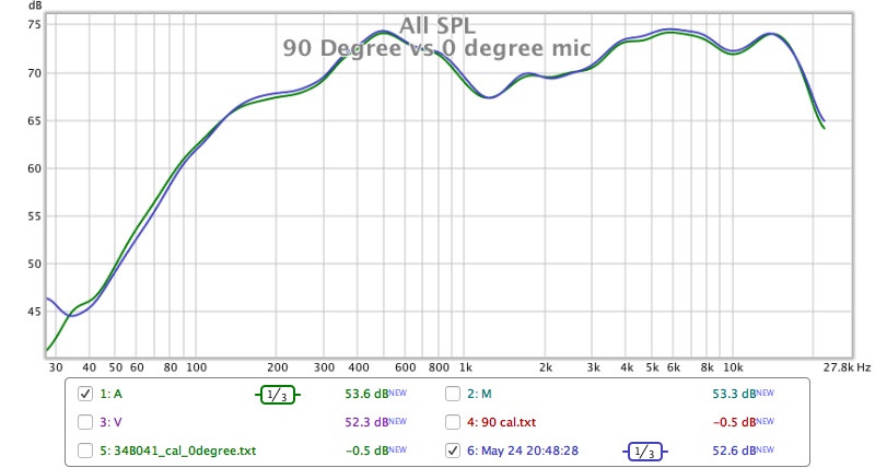
After much gnashing of teeth at excel and the formatting needed to get the cal file to work properly I got there in the end and I think it is pretty good. Here is a comparison of a measurement with the factory 0 degree file vs a 90 degree measurement with the cal file pretty good agreement.
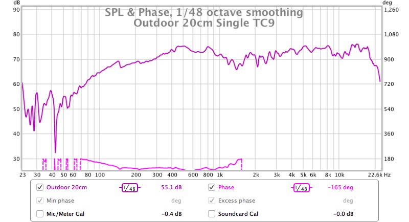
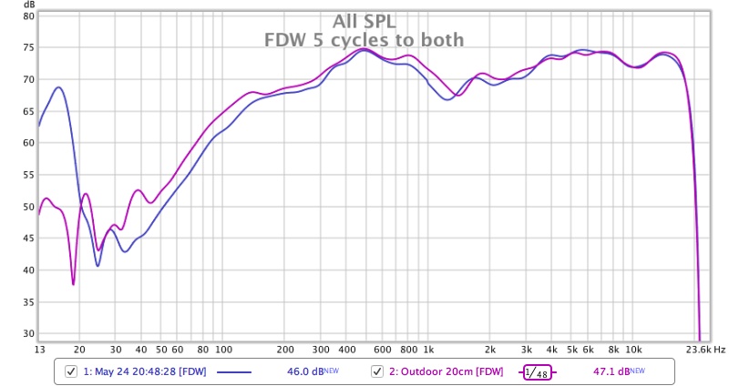
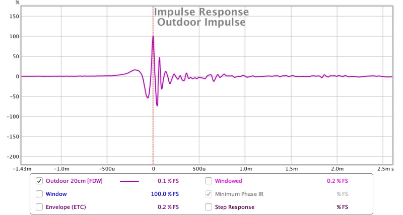
The outdoor measurement is actually better than I thought expect for the very low frequencies where the lack of output from the driver has been affected by signal to noise ratio and the road noise has corrupted it more. The outdoor impulse looks a bit funky any ideas what is going on there?
Here are some screenshots of the measurements of the Single TC9
Outdoor Single TC9 Frequency response
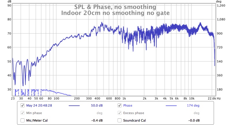
Indoor
Indoor vs Outdoor with a 5 cycle Frequency dependant window added
Outdoor Impulse
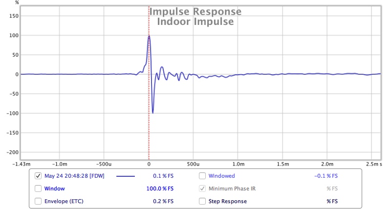
Indoor Impulse
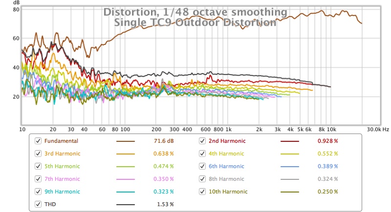
Outdoor Distortion
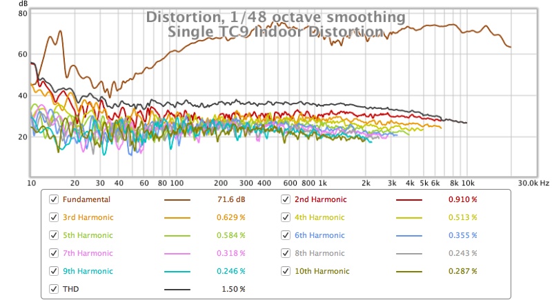
Indoor Distortion
Apart from getting familiar with the mic and REW I was using a single TC9 on a cardboard baffle so I could generate a 90 degree calibration file for my mic based on this article from John Reekie. http://johnr.hifizine.com/2014/09/how-to-make-a-90-degree-calibration-file/
After much gnashing of teeth at excel and the formatting needed to get the cal file to work properly I got there in the end and I think it is pretty good. Here is a comparison of a measurement with the factory 0 degree file vs a 90 degree measurement with the cal file pretty good agreement.
The outdoor measurement is actually better than I thought expect for the very low frequencies where the lack of output from the driver has been affected by signal to noise ratio and the road noise has corrupted it more. The outdoor impulse looks a bit funky any ideas what is going on there?
Here are some screenshots of the measurements of the Single TC9
Outdoor Single TC9 Frequency response
Indoor
Indoor vs Outdoor with a 5 cycle Frequency dependant window added
Outdoor Impulse
Indoor Impulse
Outdoor Distortion
Indoor Distortion
Attachments
-
 Single TC9 Indoor Distortion.jpg107.8 KB · Views: 1,371
 -
 Single TC9 Outdoor Distortion.jpg106.2 KB · Views: 1,367
 -
 Indoor Impulse Single TC9.jpg68.3 KB · Views: 1,383
 -
 Outdoor Impulse Single TC9.jpg71.3 KB · Views: 1,380
 -
 Indoor vs outdoor FDW.jpg84.5 KB · Views: 1,397
 -
 Indoor TC9.jpg88.4 KB · Views: 1,389
 -
 Outdoor TC9.jpg86.5 KB · Views: 1,397
 -
 90 vs 0 mic.jpg76.1 KB · Views: 1,409
That's a spooky IR for outdoors any windmills with LF rumble in the neighborhood or any military radars sweeping nasty frq, looks your measurement gear is on track when doing a campare with measurment xrk971 did at 5º in his Dagger enclosure and shared with me about two years ago, thanks X.
Attachments


Last edited:
fluid, since your array uses 5 separate chambers here's a wiring idea you could try if you feel up to the task. Make the 5 series strings using one driver from each chamber. Then put those 5 strings in parallel. You would effectively be isolating the series wired drivers from each other and it would be as if each chamber has 5 drivers wired in parallel.
Last edited:
I think you are right my cabinet is pretty well stuffed and I have run them pretty hard with 10Hz tones. There was no runaway oscillation or driver destruction. If it presents an issue it will be more subtle than that and will probably be a rise in distortion.
The main difference will be around the array's impedance peak. 10 Hz tones won't be any different. I doubt it will be forceful enough to be able to destroy a driver as we still limit the power around that frequency area anyway.
I'm mainly interested in the even load and movement on all drivers and certainly do see an advantage in the parallel wiring.
It is the frequency area where I had to work a little harder to get it where I wanted it (phase wise).
After all the work I put into my speakers I cannot neglect this new data. I'm always looking for ways to improve and the 100-200 Hz area is fun to have right both in phase and frequency. I don't know when, but I'm pretty sure I will alter my arrays after seeing these graphs.
Not looking forward to the surgery but I just have to do it. I cannot dismiss this, as I've said before, every detail counts if you want good results.
You've seen my distortion data, nothing to be afraid of if you don't alter the wiring scheme. I will take any chance of an improvement anyway. I'm just "wired" that way I guess 😀.
fluid, since your array uses 5 separate chambers here's a wiring idea you could try if you feel up to the task. Make the 5 series strings using one driver from each chamber. Then put those 5 strings in parallel. You would effectively be isolating the series wired drivers from each other and it would be as if each chamber has 5 drivers wired in parallel.
That would take even more wiring!
Interesting comments from Owen and others, but there is still no theoretical reason for preferring one wiring approach over another. Owen, were you able to prove beyond doubt that the driver blowing up was caused by the wiring scheme? Or was it just a hypothesis? None of my drivers have blown up and I have 12 drivers in a single chamber (6 in series, and 4 sets in parallel) 😱 None of Wesayso's drivers have blown up and he tortures them all the way to 17 Hz.
Wesayso,
How are your drivers currently wired and how many actual sealed chambers do you have? I seem to recall all your 25 drivers share one chamber but with smaller breather holes in between groups of them right? They sound so good now, I would hate to take them apart for some surgery that may or may not yield an audible improvement.
Regarding blowing up drivers. These are too small to hurt one another. 🙂
Just realized I said the opposite of what I meant. Need more sleep. 🙂
Fluid's setup is already series. Needs to change to parallel I meant.
Fluid's setup is already series. Needs to change to parallel I meant.
I am not sure if you wiring harness is now inaccessible or you don't want to rewire it. Series wiring is very simple if you use Faston crimp connectors - just daisy chain top to bottom +ve to -ve of successive drivers and take two ends as output. The parallel all the leads from each chamber.
- Home
- Loudspeakers
- Full Range
- Full Range TC9 Line Array CNC Cabinet