Greg, did you notice the huge change in the Step response in the example?
That long horizontal tail slowly going to zero is when it is time-coherent.
The corrected impulse did not show that kind of correction, but maybe more cycles are needed to get there. I never got that entirely but as you know I use long windows on top and bottom and shorter ones trough the midrange. But I haven't found a way to get it like I want it yet.
Could you show what an 8 cycle preset would to the STEP?
I see very positive things here, Jim does too. Just wondering what does what. We now have an almost anechoic room to play with, a luxury I don't have 😀. just kidding on the anechoic part, Jim.
I guess the low freq pre-echo is starting to rear its head here. Maybe this is pushing things to far with the linear phase PL filter? Or maybe it won't be an issue?
Attachments

I'd say this IS a problem. Still it doesn't look anything like the example shown in the documentation. I can't figure out why not...
It might be wise to back off the correction in the bass extension on this impulse from Jim. Maybe cut it off where it was in the original with 12 dB/oct below 28-30 Hz?
That might clear up what we saw down below in the waterfall. Most likely it wouldn't be exited in a convoluted song but still. It's a ported speaker you wouldn't want to boost there I think.
Last edited:
I guess the low freq pre-echo is starting to rear its head here. Maybe this is pushing things to far with the linear phase PL filter? Or maybe it won't be an issue?
My system isnt capable of clean loud output below 25hz anyway. Perhaps limiting the target FR curve to 25hz-20k would be advantageous.
I'd say this IS a problem. Still it doesn't look anything like the example shown in the documentation. I can't figure out why not...
ok, so I'll try 8 cycles with a minimum phase PL filter.
My system isnt capable of clean loud output below 25hz anyway. Perhaps limiting the target FR curve to 25hz-20k would be advantageous.
Not a problem at all. However, it will mean more gd or pre-echo in the low frequencies...
It IS fun, isn't it?
The thread is moving fast too, I'm having delay issues myself, can't keep up!
The thread is moving fast too, I'm having delay issues myself, can't keep up!
Not a problem at all. However, it will mean more gd or pre-echo in the low frequencies...
If this were the real thing, I would have to anyway. But if you guys want to experiment theoretically, then I have no problem with that.
That option is available, OK.
Here is a file to test out.
https://www.dropbox.com/s/no15ab11z628fsy/03. No photo.flac?dl=0
Cool song! I like it!
Cool song! I like it!
An Italian band called "Conqueror", from the album "Storie fuori dal tempo".
Very nicely recorded IMO.
Jim1961,
I like your Avatar - but each time I see it, it makes me say in my head, silently, "Dammit Jim, I'm a doctor not a scientist!" 🙂
I like your Avatar - but each time I see it, it makes me say in my head, silently, "Dammit Jim, I'm a doctor not a scientist!" 🙂
Great thread!
A couple of things I have found to clean up the step response if the DSP software can do it:
If multi-way speakers, use linear phase digital XO's if you can for these reasons: http://files.computeraudiophile.com/2013/1202/XOWhitePaper.pdf
Going digital XO, aside from making instant tuning changes, opens the door to driver time alignment and driver linearization.
Time alignment gives you the vertical line in the step response indicating all frequencies are arriving at the destination at the same time.
Driver linearization is correcting each individual drivers fr in the near field, before applying an overall correction at the listening position. I found this made a considerable difference, especially in my case with mid and high frequency waveguides.
"Most" small acoustic spaces have increasing decay time as frequency decreases, especially in that bottom octave and below. Looking at the waterfall chart in REW is a great way to measure. In almost every case, most folks will benefit from a HP filter at 20 Hz or fine tune once your ear/brain clues in to that low frequency long decay time. If in doubt, run REW's signal generator at 20 Hz, at a reasonable level, then click off and listen for the decay. Our ear is not very sensitive in this range, and fooled by the auditory masking effect: Auditory masking - Wikipedia, the free encyclopedia
Once the low frequency decay is tuned by a variable HP filter and slope, the step response will resemble more of the ideal triangle response. The near vertical initial step and ideally having all frequencies decay at the same rate.
Here are step responses of my right speaker measured in 6 places around a 6' x 2' grid where my couch would be:
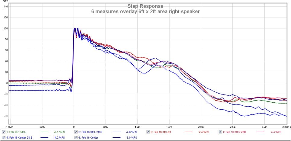
I have a small issue in the decay, switching to a waterfall display will show me which frequencies they are.
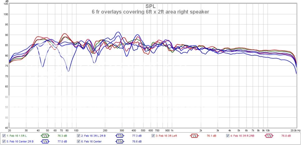
Corresponding FR at the 6 different locations 6' x 2' grid:
Here is the mdat file for one measure with the mic at the listening position: https://westcoastdx.blob.core.windows.net/upload/Feb 16 Right.zip
This measure is from over a year ago when I swapped out my HF compression driver and waveguide for another. It only contains the time alignment and overall correction and not driver linearization, which I mentioned before making a big difference. One can scroll to the linearization section in this article to see why.
I have not got around linearizing the drivers yet as 6 drivers is a lot of work. But it is worth it, especially in increasing imaging as there is a measure (proprietary to the DSP software I use) for imaging called IACC. Interaural Coherence Coefficient (IACC) which is a measure of channel and room reflection equality for the first 80 milliseconds of sound travel. Note in the article, I measure increasing IACC as I apply each filtering step, with the biggest contribution from driver linearization.
Hope some of it is useful.
A couple of things I have found to clean up the step response if the DSP software can do it:
If multi-way speakers, use linear phase digital XO's if you can for these reasons: http://files.computeraudiophile.com/2013/1202/XOWhitePaper.pdf
Going digital XO, aside from making instant tuning changes, opens the door to driver time alignment and driver linearization.
Time alignment gives you the vertical line in the step response indicating all frequencies are arriving at the destination at the same time.
Driver linearization is correcting each individual drivers fr in the near field, before applying an overall correction at the listening position. I found this made a considerable difference, especially in my case with mid and high frequency waveguides.
"Most" small acoustic spaces have increasing decay time as frequency decreases, especially in that bottom octave and below. Looking at the waterfall chart in REW is a great way to measure. In almost every case, most folks will benefit from a HP filter at 20 Hz or fine tune once your ear/brain clues in to that low frequency long decay time. If in doubt, run REW's signal generator at 20 Hz, at a reasonable level, then click off and listen for the decay. Our ear is not very sensitive in this range, and fooled by the auditory masking effect: Auditory masking - Wikipedia, the free encyclopedia
Once the low frequency decay is tuned by a variable HP filter and slope, the step response will resemble more of the ideal triangle response. The near vertical initial step and ideally having all frequencies decay at the same rate.
Here are step responses of my right speaker measured in 6 places around a 6' x 2' grid where my couch would be:
I have a small issue in the decay, switching to a waterfall display will show me which frequencies they are.
Corresponding FR at the 6 different locations 6' x 2' grid:
Here is the mdat file for one measure with the mic at the listening position: https://westcoastdx.blob.core.windows.net/upload/Feb 16 Right.zip
This measure is from over a year ago when I swapped out my HF compression driver and waveguide for another. It only contains the time alignment and overall correction and not driver linearization, which I mentioned before making a big difference. One can scroll to the linearization section in this article to see why.
I have not got around linearizing the drivers yet as 6 drivers is a lot of work. But it is worth it, especially in increasing imaging as there is a measure (proprietary to the DSP software I use) for imaging called IACC. Interaural Coherence Coefficient (IACC) which is a measure of channel and room reflection equality for the first 80 milliseconds of sound travel. Note in the article, I measure increasing IACC as I apply each filtering step, with the biggest contribution from driver linearization.
Hope some of it is useful.
How do you get your SR to go flat to the right like its a DC servo? All SR's Inhave seen before start falling down in a triangular shape - even for reportedly excellent speakers.
Hi X look the FR he is at 15Hz low extension closing in on being a DC source.
Can the REW test sweeps be augmented with DRC? If so, would measurements from them be a real world test?
Can the REW test sweeps be augmented with DRC? If so, would measurements from them be a real world test?
wesayso does this I think.
I'm going to play around with low frequency target curves when I get a chance. Then, when we agree on that, I'll process that track and you'll have a listen.
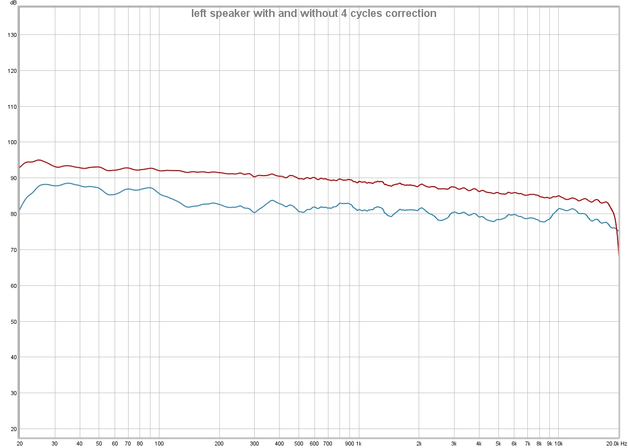
I think the 4 cycle window is enough at least to start with and perhaps enough altogether. Correct me if I'm mistaken, but it seems like GD will be 1/2 cycle or less down to at least 30hz or so.
Do you think the FR of the highpass filtered version in the attached graph will work for you? Would that be enough bass? I'm trying to avoid applying a steep filter to an already steep slope.
Do you think the FR of the highpass filtered version in the attached graph will work for you? Would that be enough bass? I'm trying to avoid applying a steep filter to an already steep slope.
Attachments

Last edited:
I think the 4 cycle window is enough at least to start with and perhaps enough altogether. Correct me if I'm mistaken, but it seems like GD will be 1/2 cycle or less down to at least 30hz or so.
Do you think the FR of the highpass filtered version in the attached graph will work for you? Would that be enough bass? I'm trying to avoid applying a steep filter to an already steep slope.
Go with the blue curve.
ok, the blue one is what I posted earlier in case I'm not being clear enough.
OK
- Status
- Not open for further replies.
- Home
- Loudspeakers
- Full Range
- Group Delay Questions and Analysis