... I am still unclear how to specify the channel width as function of distance in Akabak for the true cornu. ...
Each horn component has an exponential profile. Simply specify the throat area, mouth area and length. AkAbak defaults to an exponential profile (T=1).
Each horn component has an exponential profile. Simply specify the throat area, mouth area and length. AkAbak defaults to an exponential profile (T=1).
I would say that not all exponential curves are the same. In particular, for Cornu function, the expansion is very gentle at first near throat and rapidly expands near mouth. I don't think specifying just throat mouth and length will achieve same fidelity for the profile, which I have modeled previously using a linear conical for first 90% then switch to exponential at the end. This of course is only an approximation.
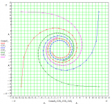
The Cornu function has the unique property that its curvature starts at zero (at mouth) and increases linearly with distance along the curve. This curve has the smoothest possible transition from straight flow to a curved flow with a radius of curvature defined by the driver chamber radius. Not sure if it matters much from acoustical modeling standpoint... but I would guess that it does.
Last edited:
Try it youself - take one of the horn sections in your plan, measure the area at 5 different points (throat, mouth, 3 points in between) and enter a 4 segment horn in Hornresp. Now enter a single section exponential horn using the same throat, mouth and total length. You should find that they are within a couple of percent in terms of volume and response. The difference is swamped by the errors caused by actually building the horn - for example, the calculated curves ignore wall thickness, which is a significant source of error near the throat in a spiral horn.
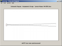
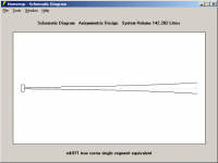
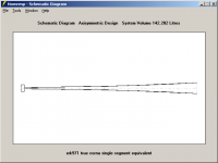
I just tried the above myself - see the attached schematics. The "measured" horn was using dimensions off your original plotted horn, for the longer horn path (from the split point to the mouth).
One area where we may differ is in the calculation of effective mouth area in asymmetric horns. I think I'll start another thread to discuss it because it's not cornu specific.
Attachments
I don't believe that severely asymmetric horn mouths are effectively as large as they appear. Draw a line from the tip of the "shorter" side of the mouth across to the nearest point on the "longer" side. That's how I measure effective mouth size, and it works out at about 6 inches, not 12. As soon as the wave is no longer confined by the shorter side, all bets are off. I've started another thread on this point, hopefully some useful discussion will occur. I'll also write some code to generate a maximum size ripple tank model. (The wavefront simulator in Hornresp only does 135x135 resolution, the original program from which it was derived goes up to 395x395.)
Don,
OK, I see your reasoning but not sure if I would agree that the longer curved side has no effect. That's a good idea to put this to the test in the ripple tank sim. If the ripple tank shows no effect of the extended curve of the mouth, I will buy it. If so, it means the expansion ratio is only half of what I thought it should be (from 30 to 1 down to 15 to 1). From how much gain we are getting in the bass, I am thinking that a 15:1 gain would not be able to achieve those levels. I think much of it has to do with the fact that the wall constrains the wave and partially forces it to continue to utilize the longer side of the mouth. It would be a simple measurement to see if the bass freq peak moves with and without wall. I think Pano has the nicest setup and may be able to help out with this experiment if he is so inclined.
OK, I see your reasoning but not sure if I would agree that the longer curved side has no effect. That's a good idea to put this to the test in the ripple tank sim. If the ripple tank shows no effect of the extended curve of the mouth, I will buy it. If so, it means the expansion ratio is only half of what I thought it should be (from 30 to 1 down to 15 to 1). From how much gain we are getting in the bass, I am thinking that a 15:1 gain would not be able to achieve those levels. I think much of it has to do with the fact that the wall constrains the wave and partially forces it to continue to utilize the longer side of the mouth. It would be a simple measurement to see if the bass freq peak moves with and without wall. I think Pano has the nicest setup and may be able to help out with this experiment if he is so inclined.
I have run an endless number of sims for the FF125WK in the 70cm side cornu, assuming a straight taper at first and a pure exponential taper.
Simulations have been run on Martin's Double BLH worksheets, with mouth ports modeled above and below the box.
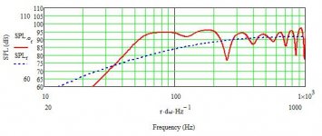
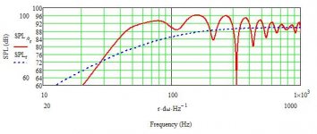
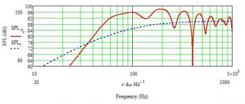
Results are below
Graph 1 is a straight taper with Throat Area= 2.23 Sd and horn length of 220cm
Graph 2 is a straight taper with Throat Area= 2.23 Sd and horn length of 280cm
Graph 3 is a conical taper with Thoat area = 1 Sd and horn length of 220cm
Graph 4 is a conical taper with Thoat area = 1 Sd and horn length of 280cm
Simulations have been run on Martin's Double BLH worksheets, with mouth ports modeled above and below the box.
Results are below
Graph 1 is a straight taper with Throat Area= 2.23 Sd and horn length of 220cm
Graph 2 is a straight taper with Throat Area= 2.23 Sd and horn length of 280cm
Graph 3 is a conical taper with Thoat area = 1 Sd and horn length of 220cm
Graph 4 is a conical taper with Thoat area = 1 Sd and horn length of 280cm
Attachments
Hajj,
Great work! Thank you for running the sims in MJK. Can you clarify: the first two plots are a straight linear taper (conical) and the the second two are exponential taper? Did you achieve the 2.23 Sd by assuming depth of channel is increased - not by changing the channel profile? My impression from looking at the sims is that the bass gain is indeed very high (matches listener observations). 15 dB gain is quite remarkable... Have you put any stuffing in these sims and I wonder how that will affect the deep dip at 250 Hz for the 220 cm one?
Can you please post the whole Mathcad worksheet screen shots, especially the horn profile definition section, and the plot showing the horn profile as a function of distance. I am also interested in the impedance and cone excursion plots.
Thanks in advance.")
On another note: I saw your post in the MJK BLH thread regarding use of Helmholtz resonators in BLH's. Would it be useful to add a Helmholtz chamber either directly underneath the main driver chamber or somewhere along the path of the main horn? This can easily be done by cutting a small hole in the back and gluing a small thin box over the hole, of course with the hole diameter and box volume appropriately sized. This may help to get rid of those main resonances beyond 300 Hz.
Great work! Thank you for running the sims in MJK. Can you clarify: the first two plots are a straight linear taper (conical) and the the second two are exponential taper? Did you achieve the 2.23 Sd by assuming depth of channel is increased - not by changing the channel profile? My impression from looking at the sims is that the bass gain is indeed very high (matches listener observations). 15 dB gain is quite remarkable... Have you put any stuffing in these sims and I wonder how that will affect the deep dip at 250 Hz for the 220 cm one?
Can you please post the whole Mathcad worksheet screen shots, especially the horn profile definition section, and the plot showing the horn profile as a function of distance. I am also interested in the impedance and cone excursion plots.
Thanks in advance.
On another note: I saw your post in the MJK BLH thread regarding use of Helmholtz resonators in BLH's. Would it be useful to add a Helmholtz chamber either directly underneath the main driver chamber or somewhere along the path of the main horn? This can easily be done by cutting a small hole in the back and gluing a small thin box over the hole, of course with the hole diameter and box volume appropriately sized. This may help to get rid of those main resonances beyond 300 Hz.
Last edited:
Exponential, sorry for the confusionHajj,
Can you clarify: the first two plots are a straight linear taper (conical) and the the second two are exponential taper?
The 2.23Sd was based on the cornu initial drawing accounting for channel width and enclosure depthDid you achieve the 2.23 Sd by assuming depth of channel is increased - not by changing the channel profile?
the whole horn is stuffed with 0.15lb/ft3 of stuffing, as for the 250hz dip, I wouldn't lose sleep over it as it's very sharp and shouldn't be a problem, especially if it's put into perspective with the rest of the horn's shortcomings.Have you put any stuffing in these sims and I wonder how that will affect the deep dip at 250 Hz for the 220 cm one?
No probCan you please post the whole Mathcad worksheet screen shots, especially the horn profile definition section, and the plot showing the horn profile as a function of distance. I am also interested in the impedance and cone excursion plots.
Thanks in advance.
I have already mentioned this earlier in this threadOn another note: I saw your post in the MJK BLH thread regarding use of Helmholtz resonators in BLH's. Would it be useful to add a Helmholtz chamber either directly underneath the main driver chamber or somewhere along the path of the main horn? This can easily be done by cutting a small hole in the back and gluing a small thin box over the hole, of course with the hole diameter and box volume appropriately sized. This may help to get rid of those main resonances beyond 300 Hz.
The resonator should help getting rid of the lower resonances should it be well designed, but will fail at taming the resonances higher in the freq range.
I already have an interesting resonator profile that should fit this application well, so if you feel like doing some mods to your enclosure, let me know
I already have an interesting resonator profile that should fit this application well, so if you feel like doing some mods to your enclosure, let me know
Yes, I am working on optimizing the enclosure from the ground up - so whatever mods that can improve things should be considered.
Thanks.
The helmholtz sizing I have right now is for the full sized 70cm cornu, I'll need to resize it for the smaller sized versions as these have a higher cutoff point, and thus accordingly need a different resonator to match the cutoff frequency.
If you send me the horn characteristics of the smaller cornucopya you have (throat size, mouth size, length) I should be able to recalculate.
If you send me the horn characteristics of the smaller cornucopya you have (throat size, mouth size, length) I should be able to recalculate.
Last edited:
Hajj,
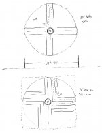
I am still in the midst of designing the next one, but it will probably be based on what I call the "True Cornu Function": 24 inches x 3.5 inches deep with the mouth size spanning the entire perimeter for an area of 24x3.5x4 in^2=336 in^2 or 2167 cm^2. The throat will be 31.3 cm^2. The driver chamber will have an area of 148 cm^2 and a volume of 1312 cm^3. The horn lengths will be 104 cm (Long path) and 49 cm (Short path) with a bifurcation. The path plan is attached.
If you can, please post the info on the resonator for the 70 cm case because many folks are interested in that size.
Thanks.
Xrk971
Attachments
Presenting the "Puck"
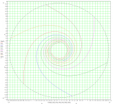
Cal Weldon had this idea for a speaker that represented one of the favorite activities of our good neighbors' up North. He called it the 'Puck' of course. Here is a True Cornu spiral horn in the shape of a disc with 6 channels. 3 of the channels are 1.26 meters long and 3 are 0.85 meters long. It can be made between 4 to 5 inches deep for use with your favorite 4 to 5 inch driver. The overall diameter of 27 inches. Since this is a true Cornu spiral with narrow channels and a small throat (32 cm^2), there will be some driver chamber compression effects. You may want to select a high efficiency driver with a more powerful motor and short stoke (think Fostex). Note that the horn mouth occupies the entire circumference of the speaker which has an area of about 2735 cm^2 for a 5 in deep cabinet to give an expansion ratio of 85!
Cal Weldon had this idea for a speaker that represented one of the favorite activities of our good neighbors' up North. He called it the 'Puck' of course. Here is a True Cornu spiral horn in the shape of a disc with 6 channels. 3 of the channels are 1.26 meters long and 3 are 0.85 meters long. It can be made between 4 to 5 inches deep for use with your favorite 4 to 5 inch driver. The overall diameter of 27 inches. Since this is a true Cornu spiral with narrow channels and a small throat (32 cm^2), there will be some driver chamber compression effects. You may want to select a high efficiency driver with a more powerful motor and short stoke (think Fostex). Note that the horn mouth occupies the entire circumference of the speaker which has an area of about 2735 cm^2 for a 5 in deep cabinet to give an expansion ratio of 85!
Attachments
My goodness you certainly don't puck around do you?
Who's going to be the first to try that I wonder? Looks rather involved in and around the centre chamber, no?
You know X, that's a far cry from what I had in mind all those years ago. Since I was thinking it would be made from plywood, I was thinking something like this:
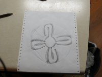
Or a more recent idea I could make from foam called the 'Daisy'.
Who's going to be the first to try that I wonder? Looks rather involved in and around the centre chamber, no?
You know X, that's a far cry from what I had in mind all those years ago. Since I was thinking it would be made from plywood, I was thinking something like this:
Or a more recent idea I could make from foam called the 'Daisy'.
Attachments
Cal,
How deep is the Daisy? Looks like fun, one only has so much foam core boards though...
For the six channel Puck, you may want to use a thinner material for the channels near the middle. So that as you say, you don't want to puck around with how difficult it will be to hot melt those narrow passages. I am thinking something like stiff carboard (like the high quality stuff used to make mattes for framing) no foam near the middle.
Regards,
X
How deep is the Daisy? Looks like fun, one only has so much foam core boards though...
For the six channel Puck, you may want to use a thinner material for the channels near the middle. So that as you say, you don't want to puck around with how difficult it will be to hot melt those narrow passages.
I am thinking something like stiff carboard (like the high quality stuff used to make mattes for framing) no foam near the middle.Regards,
X
xrk,
Do your drawings and calculations in MathCad take into account the thickness of the foam in making the spirals?
Do your drawings and calculations in MathCad take into account the thickness of the foam in making the spirals?
Cal Weldon had this idea for a speaker that represented one of the favorite activities of our good neighbors' up North. He called it the 'Puck' of course. Here is a True Cornu spiral horn in the shape of a disc with 6 channels.
Fenris,
No, the channel thickness is not accounted for. I am taking a closer look at horn design theory and the relationship between driver chamber volume & throat vs the upper cut-off frequency. I am seeing that having a too small of a throat will impact bass output. I will have to incorporate this into these spirals and its relation to the depth.
No, the channel thickness is not accounted for. I am taking a closer look at horn design theory and the relationship between driver chamber volume & throat vs the upper cut-off frequency. I am seeing that having a too small of a throat will impact bass output. I will have to incorporate this into these spirals and its relation to the depth.
Fenris,
No, the channel thickness is not accounted for. I am taking a closer look at horn design theory and the relationship between driver chamber volume & throat vs the upper cut-off frequency. I am seeing that having a too small of a throat will impact bass output. I will have to incorporate this into these spirals and its relation to the depth.
The added thickness will change the geometry. 3/16" isn't much of a difference at the 24" opening, but it's a huge difference with a 3/4" wide passage. The dimensions will no longer be an exponential horn Each "lap" around that the spiral does adds that much to the overall size. Plus it subtracts linearly from the cross-sectional area at each point.
The added thickness will change the geometry. 3/16" isn't much of a difference at the 24" opening, but it's a huge difference with a 3/4" wide passage. The dimensions will no longer be an exponential horn Each "lap" around that the spiral does adds that much to the overall size. Plus it subtracts linearly from the cross-sectional area at each point.
You are right about the thickness being more important towards the middle where the spacing is smaller. It is easy enough to put a thickness offset into the Mathcad equations used to generate the spirals. I am more concerned about having too narrow a throat right now with the true Cornu function. I may have to accelerate the spiral to get wider spacing towards the middle.
- Home
- Loudspeakers
- Full Range
- Ever think of building a Cornu Spiral horn? Now you can!