Hello everyone. So i started learning about electronics slowly, my physics knowledge is really bad but i hope i can fix that.
This is my second electronics project so i decided to do something cool... http://www.electro-tech-online.com/imgcache/8472-14.gif
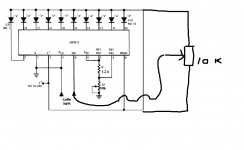
I end up doing this, i have no idea how it works and i barely connected everything to my breadboard.
I use 9V power source
3,5V , 0,02A 10leds
10k potenciometer
and 1k(didint have 1,2k) resistor exactly as shown in the scheme.
everything seemed to work fine but when i play music only 5 or 6 leds are glowing and the last 4 are not doing anything ;/ Whats should be wrong?
I tryed to read lm3915 description but there is so much information my head almost blew up :/ there is no way i can understand something with brains like mine, so i hope u got some simple explanation how to fix that")
This is my second electronics project so i decided to do something cool... http://www.electro-tech-online.com/imgcache/8472-14.gif
I end up doing this, i have no idea how it works and i barely connected everything to my breadboard.
I use 9V power source
3,5V , 0,02A 10leds
10k potenciometer
and 1k(didint have 1,2k) resistor exactly as shown in the scheme.
everything seemed to work fine but when i play music only 5 or 6 leds are glowing and the last 4 are not doing anything ;/ Whats should be wrong?
I tryed to read lm3915 description but there is so much information my head almost blew up :/ there is no way i can understand something with brains like mine, so i hope u got some simple explanation how to fix that
Welcome to diyAudio
It sounds like you haven't enough signal to drive the device fully. Does altering the preset resistor in your diagram not give enough gain ?
For this to work best you really need another stage in front of this to condition the signal and detect and "hold on" to peaks so that the display becomes much slower and more readable. Applying AC (your audio) means the display is trying to respond to quickly and will be dim and poor in use.
Have you got the data sheet ? That shows a couple of very simple rectifiers, one using a transistor and one an opamp.
So what do u mean exactly.I posted the data sheet of mine. I played with pot but that didint help.. Setting it to max only 2-3 led glow and setting to 0 , 5 -6. One more interesting fact is that when i connect to resistor to pin 6 isntead of pin 7 all leds starts glowing to music but not good.. Some are bright and some are not bright at all.
Type LM3915 into the blank search box here to get the manufacturers data sheet,
Datasheet catalog for integrated circuits, diodes, triacs, and other semiconductors, view
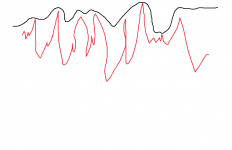
Your circuit is responding to an audio signal that varies really quickly. For the LED's to be readable and usable you need to track that audio signal and convert it to a more clowly changing one.
Imagine the red signal is the audio. You need to rectify and "hold" that signal to get a more usable input signal for the LM3915. The black line shows what that signal might look like and that would drive the LED's more slowly and accurately.
Datasheet catalog for integrated circuits, diodes, triacs, and other semiconductors, view
Your circuit is responding to an audio signal that varies really quickly. For the LED's to be readable and usable you need to track that audio signal and convert it to a more clowly changing one.
Imagine the red signal is the audio. You need to rectify and "hold" that signal to get a more usable input signal for the LM3915. The black line shows what that signal might look like and that would drive the LED's more slowly and accurately.
Attachments
You need a grasp of the basics. A rectifier converts AC (thats your audio) into "DC". The simplest device for that is a diode but there are a couple of reasons why we would not just use one "as is".
Look at the diagrams of what the diode does,
Rectifier - Wikipedia, the free encyclopedia
The problem with a simple diode is that there is a 0.7 volts "dead zone" where nothing happens... so we use other parts (the opamp) to overcome that and make a precision rectifier.
For your usage the simple one transistor example would be a good starting point because it needs no additional power supply, just the supply the LM3915 is running on. The transistor can be any general purpose PNP device.
You need to look at the data sheet.
A feature not completely illustrated by the block diagram is the LED brightness control. The current drawn out of the reference voltage pin (pin 7) determines LED current. Approximately 10 times this current will be drawn through each lighted LED, and this current will be relatively constant despite supply voltage and temperature changes.
So you need to measure the voltage on pin 7 and calculate the current (ohms law) taking the resistance as R1 + the preset pot value as set. Say you measured 3 volts and the preset was 4k. The current would be 3/(1200+4000) which is 0.57milliamps. To increase the current and keep everything else the same you alter the ratio of the resistors. Say you made R1 equal 120 ohm and the preset 400 ohm. Now you have 3/(120+400) which is 5.7ma. Ten times as much.
Mooly, you can brink a horse to a water...
but self illuminating displays must be LED
Thanks that helped!so if i calculate the current and for example its 1mA so i need to split it into 10 because i have 10 LED's? so i will have 0,1mA for every led? is there any way to measure the voltage on pin 7 if i dont have voltmeter? If my leds are 20mA so that means i need to reach about 20mA per each led so that way leds can glow perfectly? sorry for those questions :/
According to the data sheet, the calculated current applies to each LED, its not shared. One error I made... the current calculated is actually ten times less than the LED current. So that means if you calculate it out at 0.5 milliamps then the LED current is actually ten times that, or 5 milliamps.
I thought the figures looked at little small, I should have read the application notes more carefully.
I thought the figures looked at little small, I should have read the application notes more carefully.
I know you are feeding this with audio. Why don't you rig the input up to a variable DC voltage and see how the LED's behave. Try something like a 10k variable resistor across the power supply and connect the wiper to the input. Turning the preset should illuminate all the LED's and you can judge the brightness better that way.
I think your big problem is just feeding audio into this... you need to precondition the signal with the rectifier and hold circuit we mentioned earlier.
I think your big problem is just feeding audio into this... you need to precondition the signal with the rectifier and hold circuit we mentioned earlier.
If you rig a variable resistor up like this then the LED brightness can be gauged. The LED's will all light as you alter the preset.
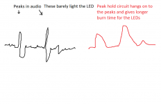
When you are feeding music into the device the peaks of the signal are fleeting, they last only a millisecond or so. That is to fast for the circuit to display them. What you need is a circuit that track the audio and converts it to a more slowly varying voltage.
Look at the diagram to see how a circuit would handle a peak.
Attachments
Its a variable resistor. The value isn't critical, anything from 10k to 100k would be fine. The middle leg of a preset is the "wiper" or moving contact. That is the one that connects to the 3915 input. Connect one of the end pins to the positive supply and the other to the 0 volt point as shown. If you reverse the end connections then the control will work "back to front".
Trying to explain common electronics to a newbie is always a challenge. You could try reading through some of Rod Elliot's pages as he is quite good at explaining things in basic terms.
Precision Rectifiers
Precision Rectifiers
- Status
- This old topic is closed. If you want to reopen this topic, contact a moderator using the "Report Post" button.
- Home
- General Interest
- Everything Else
- lm 3915 vu meter problem.