Hi all,
I'm looking for a simple/cheap way to plot tube curves, and have a spare hickock I177b transconductance meter sleeping there.
(here a link to the schematic ----> http://www.suertenich.com/html/tester/i177.gif )
I also own the expansion box MX949 that allows any pins connection
My basic idea is to apply a stairsteep signal to the grid, while a rectified AC is sent to the plate ( also used as X deviation )
Y would come from a sense resistor.
It would also be nice for a future project to reuse those outputs to feed a computer interface.
Any Suggestions ?


Hi, my first attemps are very impressive !
Topology allready works (tested with low voltage ECC86), not used yet the tester but two DC supplies (logic for stairstep + filaments) and an AF generator (AC sweep).
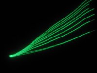
The curve is clear and very instructive (you can see them moving as filament voltage change for example).
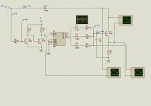
Here's my test sample schematic:
(thanks to Kazuhiro Sunamura (---> http://www.intio.or.jp/jf10zl/) for the idea !)
PS: the spice schematic shows a transistor being tested at the right, I've breadboard it and tested it with both transistors and tubes (ECC86 & ECC83) AF gen feeding a step up transformer for VA >50V, stairstep fed to the grid via a tel line transformer (can provide different bias offsets for the stairs.)
Topology allready works (tested with low voltage ECC86), not used yet the tester but two DC supplies (logic for stairstep + filaments) and an AF generator (AC sweep).
The curve is clear and very instructive (you can see them moving as filament voltage change for example).
Here's my test sample schematic:
(thanks to Kazuhiro Sunamura (---> http://www.intio.or.jp/jf10zl/) for the idea !)
PS: the spice schematic shows a transistor being tested at the right, I've breadboard it and tested it with both transistors and tubes (ECC86 & ECC83) AF gen feeding a step up transformer for VA >50V, stairstep fed to the grid via a tel line transformer (can provide different bias offsets for the stairs.)
Attachments


EC8010 said:Sadly, curve tracers are difficult. Often, you see equipment that is overly complex, but getting the complexity of a curve tracer down to manageable is difficult. Every time I look at the idea, I turn away...
Actually, once you figure out the retrace blanking it isn't that difficult to implement with a scope -- the second issue of Glass Audio had such a circuit in which grid voltage was stepped with a CMOS clock.
There are, however, any number of data acquisition cards which allow you to both control voltages and measure VI -- and dump the data into excel for analysis -- the beauty of employing one of these, even with an inexpensive tube-tester (like an Eico or Heathkit) is that all the nasty wiring is already done. once the data is in excel all the useful information can be calculated -- and you can compare multiple devices for matching.
with regard to a "Sound Card" -- better make sure you put some protection on the output or you will quickly fry the caps -- and sound cards don't take well to DC inputs anyway -- if you can get a copy of the July 2006 Dr. George Steber had an article in the ham radio magazine QST describing a sound-card based IV tracer. A local ham radio club in France should have a copy.
jack
bembel said:. . .
Here's my test sample schematic:
(thanks to Kazuhiro Sunamura (---> http://www.intio.or.jp/jf10zl/) for the idea !)
. . .
And thanks to you for pointing at
 (Great link !)
Yves.
Jack, the soundcard doesn't need to see DC. A good workaround is to apply an offset sinewave with a moderate frequency (say, 500 Hz) to the plate, with the troughs reaching some low voltage or zero and the peaks reaching the max voltage of interest. This can be done with a simple HV amplifier driven by the soundcard.
At the same time, apply a 510 Hz offset sinewave (running from zero volts to cutoff) to the grids.
Using the soundcard input, measure the AC current through the plate/cathode via a small sensing resistor.
If you are generating these waveforms via software, then all the timings are known and a complete set of tube curves can be constructed in about 0.1 second. Running a full second allows averaging for lower noise.
I'm rather software stupid, so this has sat in a drawer for about forever without getting done.
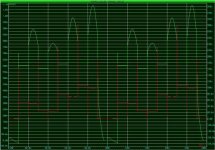
Here are the stairsteps outputs V *green* & I *red* (loaded by a transistor base). It's close to the breadboarded circuit.
- Now we have to smooth the spikes ! (Although the X/Y traced curve is nice)
I add the cap to smooth the voltage stairs, but signal could be better I think ? Will a buffered output help ?
- The two first transistors (which make a 50% duty cycle clock for the 7490 Decade counter) may surely be replace by something else able to withstand a high voltage input (let's say 500V peak) OPamp circuity? optocoupler ???
- Amplifiy the stair output providing adjustable step amplitude, polarity, and maybe, offset too ( is an OPamp OK for this ? is it more elegant than the transformer approach ?)
- How can we modify the system to be, on demand, a voltage source or a current source ?
- It's amazing to see that you can kinda "focus" the trace by tuning a sweet frequency (AC & clock) usually around 500Hz far better then 50Hz or 25Hz (europe speaking), in fact it synchronise the returns I think ?
Your help will be greatly appreciated (OPamps are new to me !)
PS: It's too bad I've forgot my photo memory card, and can't post you scope screenshots for now (but soon I think).
Attachments
SY -- couldn't you just modulate the cathode -- one of the simplest amplifiers I ever made was using the adjust pin of an LM317.SY said:Jack, the soundcard doesn't need to see DC. A good workaround is to apply an offset sinewave with a moderate frequency (say, 500 Hz) to the plate, with the troughs reaching some low voltage or zero and the peaks reaching the max voltage of interest. This can be done with a simple HV amplifier driven by the soundcard.
The soundcard inputs are DC protected anyway -- sort of -- opamps are cheap protection, or clamping diodes. Steber previously wrote the article for Circuit Cellar, but improved the software for the QEX/QST article.
The software can be found in this zipped file:
http://www.arrl.org/qexfiles/06_July/7x06Steber.zip
there is a treasure trove of goodies on the ARRL site -- andsometimes they have PDF's of their articles:
www.arrl.org/qexfiles
couldn't you just modulate the cathode
You mean instead of the grid? Why? To use the 317? Sure, you can do that and account for the Vgk deviation in software. You'd need to build in a -1.25V or slightly greater offset to get Vgk down to zero.
Hmmm, if you did it at 60 Hz and modulated the grid at 65, you'd lose some resolution and the measurement won't have as many averages in a given time, but the HV sweep circuit becomes even easier.
By jackinnj:
I read it Jack, as your posts here too. And I'm glad to read you again about this subject!
By SY:
SY your idea seems very interresting, but I don't understand really what's about with this kind of "modulation" beetween signals, how to trace something without clear steps ?
(PS:Stuart, I'm still waiting a little mail from you about my few questions regarding old articles)
By Yvesm:
Yves, are they real traced curves ? if, then how is the hardware setup ?
Have you a shot of your stairs ?
Finaly
By EC8010:
"...And come back !" A shared feeling, isn't it ?
The basic tube tester idea is meant to have "modular" system, basic elements with I/O. As you said the tube tested is allready cabled (the extension box with plugs is very handy too), the idea that X/Y BNCs could plug into a scope or an external computer adapter box please me very much.
Dr. George Steber had an article in the ham radio magazine QST describing a sound-card based IV tracer
I read it Jack, as your posts here too. And I'm glad to read you again about this subject!
By SY:
A good workaround is to apply an offset sinewave with a moderate frequency (say, 500 Hz) to the plate, with the troughs reaching some low voltage or zero and the peaks reaching the max voltage of interest. This can be done with a simple HV amplifier driven by the soundcard.
At the same time, apply a 510 Hz offset sinewave (running from zero volts to cutoff) to the grids.
SY your idea seems very interresting, but I don't understand really what's about with this kind of "modulation" beetween signals, how to trace something without clear steps ?
(PS:Stuart, I'm still waiting a little mail from you about my few questions regarding old articles)
By Yvesm:
As is, it allowed me to write an application in VB which can do that:
Yves, are they real traced curves ? if, then how is the hardware setup ?
Have you a shot of your stairs ?
Finaly
By EC8010:
Every time I look at the idea, I turn away...
"...And come back !" A shared feeling, isn't it ?
The basic tube tester idea is meant to have "modular" system, basic elements with I/O. As you said the tube tested is allready cabled (the extension box with plugs is very handy too), the idea that X/Y BNCs could plug into a scope or an external computer adapter box please me very much.
bembel said:"...And come back !" A shared feeling, isn't it ?
I'm clearly going to have to look at this again and go for a simpler approach...
Hi SY,
Euh ? Something like a "sub carrier" or "chopper"??
I've solved this problem by software, since plate voltage and current both remain at zero volts by half the period, we have the DC reference !
The hardware setup is the posted schemo.
No snapshot available now, as said, steps are not precise enough.
I've 9 steps quite evenly spaced for 9 Volts and the "0V" one is in fact near 0.5 due to the thyristor saturation voltage.
Apart for building a case with various sockets and selectors, the stairsteps generator IS the main problem it remains to solve.
Yves.
SY said:Jack, the soundcard doesn't need to see DC. A good workaround is to apply an offset sinewave with a moderate frequency (say, 500 Hz) to the plate, with the troughs reaching some low voltage or zero and the peaks reaching the max voltage of interest. This can be done with a simple HV amplifier driven by the soundcard.
Euh ? Something like a "sub carrier" or "chopper"??
I've solved this problem by software, since plate voltage and current both remain at zero volts by half the period, we have the DC reference !
Yes, they are !bembel:
Yves, are they real traced curves ? if, then how is the hardware setup ?
Have you a shot of your stairs ?
The hardware setup is the posted schemo.
No snapshot available now, as said, steps are not precise enough.
I've 9 steps quite evenly spaced for 9 Volts and the "0V" one is in fact near 0.5 due to the thyristor saturation voltage.
Apart for building a case with various sockets and selectors, the stairsteps generator IS the main problem it remains to solve.
Yves.
bembel said:Yves,
I want to test your stairstep circuit can you give me some strarting values for C1-2, R2-7 ? please
At present time, C2 is 10µF and R2 is a 200K pot with a 100K fixed in serie.
D6 is a 9.1V zener.
Oh, and actually, thyristor, cap and zener return to the cathode, not to ground.
Have fun
Yves.
I'm still waiting a little mail from you about my few questions regarding old articles
That request has been officially lost in the clutter and my current obsession (a phono stage). Remind me of what it was and I'll hop to it.
- Status
- This old topic is closed. If you want to reopen this topic, contact a moderator using the "Report Post" button.
- Home
- Design & Build
- Equipment & Tools
- Modifying a tube tester into a curve tracer (oscilloscope X/Y outputs) ?