Regarding DEREE IR/USB packages, yes I have too of those.
And I would suggest you to get the real thing, DE-5000 software it is remarkable.
Other than it features, it can transform a regular computer monitor to look as bench-top LCR..
I have a DE-5000 and am interested in the IR/USB option.
What features have you found most useful in the software?
Any one know if the DE-5000 optical to USB link is the same one used on
the Fluke Scope-meter? I'm thinking it is a standard link type link?
The only brand of data cable that I do not own so far, so to test it, is one from FLUKE
There is three or four types of chips (for use in a data cable) that T&M brands using for this job.
Agilent and HIOKI using so far compatible communication chips in their cables, but even so the distance of the LED lens is very critical.
The housing of the IR-USB (module) it must 100% compatible too or else it does not work :
a) LED to near by LED distance.
b) LED to facing LED distance.
c) Even escaping daylight can make this connection as problematic too.
Also many data logging software they do ignore (when trying to auto connect with a IR-USB cable) any similar devices that is not recognized as their own.
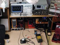
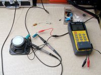
Came across a great use for the device today. I have this old filter/inductor/choke from an old centrifuge. It is pretty large, I put it next to the DE5000 for comparison. There is pretty much no information but it was connected directly to mains. The iron laminations indicate as expected its a filter for mains frequency. I decided to see if I could get a reading on it at 120Hz.


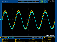
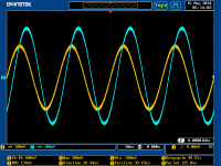
So let's see how it does:


Clearly its a 10000uH inductor., but I also can characterize is DC resistance and series resistance.


We can also watch the inductance drop as the frequency increases.
By getting its various values I know enough about this inductor for it to be useful if I want to use it in a design. Surprise surprise an lcr is good for characterizing an inductor
So let's see how it does:
Clearly its a 10000uH inductor., but I also can characterize is DC resistance and series resistance.
We can also watch the inductance drop as the frequency increases.
By getting its various values I know enough about this inductor for it to be useful if I want to use it in a design. Surprise surprise an lcr is good for characterizing an inductor
Surprise surprise an lcr is good for characterizing an inductor
If you do the same frequency scaling by using an speaker instead, you will note another one remarkable detail.
Unfortunately DE-5000 does not have 20KHz range for this experiment.
Last edited:
If you do the same frequency scaling by using an speaker instead, you will note another one remarkable detail.
Unfortunately DE-5000 does not have 20KHz range for this experiment.
okay Kiriakos, we are waiting...
...don't have a working LCR meter yet, but will you show us, efkharisto?
I can not help because now I have advance regarding classroom and now I am discovering the world of capacitors.
There is an animal called as Bipolar and I am questioning it so to find the truth.
What I discovered so far is that imitations of Bipolar by using two polar electrolytic capacitors’ instead, causes large phase change and have significant losses.
Basically any combination of two capacitors in series causes a phase change.
But two Bipolar connected in series has much less losses, which now I am thinking that I can combine them so to create my own custom values regarding smaller capacitance.
What DE-5000 helped me to verify, is the capacity loss when two capacitors are in series.
Attachments
Not very good in fact: for iron, the initial permeability will be quite different from the amplitude permeability, and also from the incremental permeability if you use it in filter circuits.Surprise surprise an lcr is good for characterizing an inductor
Anyone happen to know what the small potentiometer in the DE-5000 is for? Also, any info on a calibration process? I have a very accurately measured standard cap and would like to tweak my DE-5000 to the standard cap's value -- it is now in error by about 0.04% at 100nF. I am afraid that a cal is unavailable, set by the fixed internal blue cap near the pot. Comments?
There is no documentation for the internals of DE-5000 and this is something usual those days.
Regarding the tiny pot I would suggest to not play with it.
The meter is capable for test leads calibration which is sufficient for perfect results regarding ESR.
Also the meter accuracy it should be inspected at specific temperature and after been powered for 20 minutes.
Therefore only the ones who own the power pack can come close to reliable conclusions.
As kiriakos mentioned, info about the circuitry in these LCR meters is hard to find indeed. One bit of additional info can be had in the skimpy datasheet for the main Cyrustek chipset in the DE-5000 (attached).
I found the following in the datasheet on the subject of calibration/accuracy...
"All accuracy is guaranteed by proper ratio resistor calibration and open/short calibration. All accuracy is guaranteed for 10cm distance from VDUTH/VDUTL pins of ES51920."
To achieve the maximum stated accuracy of the DE-5000 it looks like the component under test should be plugged directly into the test slots on the face of the meter, or use extremely short kelvin connection test leads.
Also, I see that the stated accuracy of the DE-5000 on the 200nF range (@100KHz test freq.) is 0.6% + 3 counts.
The original reason that I downloaded the chipset datasheet a while back was because I was curious about the 10 capacitors that are installed in the more expensive IET branded DE-5000, but are missing in the value priced DER DE-5000. There are 7 missing 10uF/10V tantalum capacitors (C31, C32, C35, C36, C40, and C46) and 3 missing ceramic chip caps (C17, C18, and C19).
My DER DE-5000's PCB without the capacitors installed is marked REV.8. The IET DE-5000 PCB that I saw in a video by Dave Jones, which had the caps installed, was REV.5. I can only assume that they were not deemed critical to the accuracy of the LCR meter. I bought the 10uF/10V tantalums in case I decide to install them at some point in the future. Unfortunately, I have no idea what the component values of the 3 missing ceramic chip caps are.
Regards,
Frank
p.s. Mr. Moore, I found your articles about modding the Heathkit IG-18 excellent and very useful to me.
Attachments
Ceramic chip caps is an additional filter which it can been removed when proper corrections has been made in the firmware of the LCR or by correcting the traces over that PCB by another PCB revision.
DEREE Electrical instruments LTD deserves the right to make changes, and it is not an issue of cutting corners in the magnitude of few American cents.
I am having the old revision of PCB which does not have battery polarity protection, but I do not care about that, it is almost impossible due it battery case design to install the battery the other way around.
Last edited:
Actually, the three tiny missing ceramic chip capacitors were of a minor concern, but the seven missing 10uF tantalum caps did get my attention. I was hoping that the datasheet for the Cyrustek chipset had a suggested circuit, like datasheets usually do, so that I could see if Cyrustek included the tantalums in their example circuit. No such luck.
It's surprising how low the price has fallen on ebay for the DER DE-5000.
Regards
It's surprising how low the price has fallen on ebay for the DER DE-5000.
Regards
It's surprising how low the price has fallen on ebay for the DER DE-5000.
Regards
I am aware of the FOB price and the only thing that I am going to say is that this meter with it original case and all accessories has a stable pricing in Asia.
The meter with out all it accessories looks like crippled.
From the other hand IET as distributor in USA played a game in the back of consumers.
And this game is also played by Agilent too.
And I am fighting such games due my Blog.
Last edited:
Wow! I just started reading this and I am amazed at the low price.
I needed to measure ESR at 100kHz instead of the usual 100Hz or 1K so I "bit the bullet" and I purchased a B&K 886 a few years ago. It appears this meter will do everything my B&K will do for a whole lot less. Please keep us informed on how reliable this meter turns out to be.
I needed to measure ESR at 100kHz instead of the usual 100Hz or 1K so I "bit the bullet" and I purchased a B&K 886 a few years ago. It appears this meter will do everything my B&K will do for a whole lot less. Please keep us informed on how reliable this meter turns out to be.
Please keep us informed on how reliable this meter turns out to be.
How many years old feedback do you need ?

This is an 2011 product, my sample arrived at 21 November 2012,
In three months will be two years old.
LCR DE-5000 from DER EE Taiwan, Teaser photos 22/11/2012 ITTSB.EU
Well there is interesting equipment for that, they are called calculators. Don't forget to add shipping cost twice (if they charge you for that). Make 2 calculations, one with the bare meter and a separete order for the TL21 etc. and a second one for the whole shebang. Now compare. The cheapest option would seem best for your wallet.
Before all that first ask yourself what you can do with just the meter.
Before all that first ask yourself what you can do with just the meter.
Last edited:
- Status
- This old topic is closed. If you want to reopen this topic, contact a moderator using the "Report Post" button.
- Home
- Design & Build
- Equipment & Tools
- Der EE DE-5000 true LCR (100kHz)