Sorry, I've just noticed that the third spectrum somehow did not make it. Here it is:
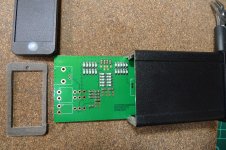
That's a neat board. I just bought 2.
I think step 1 is to lower the operating level. 6V RMS is too high. It should be around 3V max. The tuning caps could also be a limitation but other aspects first.
can you reverse engineer the circuit? I'll do it when it gets here but sonner would allow more refinements faster.
When I get it I'll set up the Shibasoku and the passive notches and see what I learn.
At this moment I have only the results, that you can see in my post #5199Have you tried C0G capacitors?
These results are not the worst, which I saw in some earlier experience. Seems, that COGs may have different performance, also maybe within the one type and the nominal.
Maybe higher voltage COGs are better, I do not know.
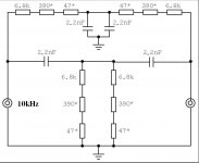
I fouund the schematic which doesn't show well on screen. However I see seveal options for improvements:
1) The Reference for the output voltage comes from the negative supply. That should be revised and maybe made adjustable. A 25K pot from - rail to ground with the 2.2 MOhm resistor to the wiper might work
2) A series resistor on the FET to reduce its control to just a little more than necessary to stabilize the output will alo redice any distortion from it.
Its a pretty textbook example of a state variable oscillator it seems. Even with rework, making it with through hole parts makes it a candidate for tweaking.
I'm not confident that it will get to the level of Victors oscillators. It will be interesting to play with.
What's the noise like with this?
David:
Per request here is the spice file and the refised mosfet and jfet files. Replace the existing files in the libs directory and it should work. Adding IC's is more complex.
In the simulation- its for a phono preamp with chopper stabilization. It works quite well. NuForce changed a lot before this ever went into production.
The input block creates a phono equalized signal. I forgot where I lifted that piece but it works really well. The chopper is a standard LTC part. I was going to use a different part and solution since I don't have a +/- 15V supply to work with. Its a lot of parts to do the task.
If there is interest I'll dig out the tweaks to make it run as a flat amp at 20 dB and at 6 dB. I can't find the original spice files any more.
Attachments
At this moment I have only the results, that you can see in my post #5199
These results are not the worst, which I saw in some earlier experience. Seems, that COGs may have different performance, also maybe within the one type and the nominal.
Maybe higher voltage COGs are better, I do not know.
Ah yes sorry, I forgot about your earlier post.
David:
Per request here is the spice file and the refised mosfet and jfet files. Replace the existing files in the libs directory and it should work. Adding IC's is more complex.
In the simulation- its for a phono preamp with chopper stabilization. It works quite well. NuForce changed a lot before this ever went into production.
The input block creates a phono equalized signal. I forgot where I lifted that piece but it works really well. The chopper is a standard LTC part. I was going to use a different part and solution since I don't have a +/- 15V supply to work with. Its a lot of parts to do the task.
If there is interest I'll dig out the tweaks to make it run as a flat amp at 20 dB and at 6 dB. I can't find the original spice files any more.
Thanks Damian.
Runs perfectly.
Yes, we can see relative changes, but sometimes we can go to the wrong conclusions. Sometimes harmonics from different parts of the system play with each other, especially the second harmonic.
In my own way, first step, when I use unknown ADC, is reducing the input signal from the reliable sine source for the ADC to the point, when harmonics become invisible. Also needs to check, if no artifacts at lower levels. If all is ok, then this would be the max input (0dB) for this ADC. Next step is to use twin T notch and the buffer amplifier at the ADC input. The quality of the twin T filter parts, is very the important thing. Only metal film resistors and perfect polypropylene or polystyrene capacitors (or maybe rare other types) can be used. I can recommend Wima FKP2 or polystyrenes from LCR.
Regards.
I agree completely -
The numbers below about 100-110 are all worthless data with sound card type instruments. The phase changes of very small amount will give completely different harmonic data. I agree, it may look like you are making relative data changes only but that is not true. Only careful testing (VERY careful) need to be made for accurate harmonic data beginning at about -100dB re 1 v.
THx-RNMarsh
Last edited:
I've tried searching Ebay for Victors oscillators without success. Is there a link I can follow anyone?
Thanks, Chris
Best i can do.
Ultra low distortion ( | eBay ???????
I've tried searching Ebay for Victors oscillators without success. Is there a link I can follow anyone?
Thanks, Chris
At this time I have only two 10kHz boards in stock:
Ultra low distortion ( 0.00005%) 10kHz sine generator assembled and tested PCB | eBay
1kHz would be available approximately after one week. Unfortunately I can't offer generator boards in big quantities, because it needs hand work and relatively much time - the opamps noise checking, components matching, soldering, adjusting, cleaning, testing the performance. As result, sometimes all the boards are out of the stock, but you always can ask me about the terms.
Regards.
We all need a twin tee board from some enterprising person. There are oscillator options but the critical test part is elusive. I'm too busy working to have much time but maybe someone else (or one of the really enterprising China guys) is up for this. Even if I need to load the tuning components and tweak it it would save a lot of time. Maybe matching simple software that can do the corrections and calculate the various distortion numbers. At these levels were not testing too many amplifiers. Very few are anywhere near this good. But you can always integrate it with a load resistor.
Dummy Load: FWIW I got a couple of these 8 Ohm 100 Watt resistor for dummy Load : 2pcs per lot | eBay and mounted them on an old heat sink. They really are non-inductive to 140 KHz (the upper limit of my ESI videobridge) and really cheap.
Dummy Load: FWIW I got a couple of these 8 Ohm 100 Watt resistor for dummy Load : 2pcs per lot | eBay and mounted them on an old heat sink. They really are non-inductive to 140 KHz (the upper limit of my ESI videobridge) and really cheap.
Hi Demian, vicnic,
Perfect! Many thanks.
vicnic, I have to save up for these anyway. Count me as extremely interested in both 1 KHz and 10 KHz versions. I put one in my "cart" so I can find them again. If you sell out, I'll simply pay for a pair in advance and wait. No problem.
Demian,
I bought the original Dale 8R, 250 watt resistors and had them mounted on milled heat sinks. It cost me $50 each (in the 80's) and another $50 to have each heat sink milled flat for mounting. So these are cheap! Really cheap. Anyone who needs dummy loads should jump on these.
Just think, I watched one of my guys blow one up after doing something I told him not to do. He was running a Yamaha P-2200 bridged on one resistor - Crack .... plop as one end eased out with a puff of smoke and fell down. That was an expensive laugh. That one cost me $60 for the resistor only by then. At least I know how they are made now.
If I were to do it over today, I would use 7.5 ohm value and pad the rest taking into account resistances. They are going into a panel soon. But for people who will measure directly across these, they are perfect.
-Chris
The resistors were an experiment. I was expecting serious inductance but found little enough that they went into service. I also have an array of 8 of the 250W 1 Ohm noninductive Dales but its BIG. I would pop the main breaker before they got hot.
The China resistors do need a heat sink to meet the ratings.
The China resistors do need a heat sink to meet the ratings.
Chris,
I prefer 8 ohms and parallel a trim resistor. I usually buy my load resistors as surplus. My biggie is 8 225 watt 8 ohm resistors all going to binding posts so I can adjust the load value. In use I have melted the insulation on the connecting cable.
Demian,
I have 400 amp 3 phase service so I don't have to worry about mains supply. Interestingly enough since my service is shared with residential customers my single phase runs around 127. That way I get 208 3 phase and they get 220 single phase or close enough for both.
Samuel Groner offered his twin T design to the interested in this thread a while ago. I got the Gerbers and the design note from him, and here is my - not yet finished - example.We all need a twin tee board from some enterprising person. There are oscillator options but the critical test part is elusive. I'm too busy working to have much time but maybe someone else (or one of the really enterprising China guys) is up for this. Even if I need to load the tuning components and tweak it it would save a lot of time. Maybe matching simple software that can do the corrections and calculate the various distortion numbers. At these levels were not testing too many amplifiers. Very few are anywhere near this good. But you can always integrate it with a load resistor.
Regards,
Braca
Attachments
- Home
- Design & Build
- Equipment & Tools
- Low-distortion Audio-range Oscillator