In some cases it does.
I tested some alternatives to the LME49990 for my Audio Analyzer. Among them OPA1611.
With the LME49990 i can get loop back distortion at 1 kHz below -130dB. Replacing one op-amp (output driver, in a combo with LME49600) gave me a loop-back distortion of -123.7dB. The input amp and the ADC driver still used the LME49990.
Some of the other alternatives performed slightly better than the OPA1611. The only one that was on the same level as the LME49990, and perhaps even slightly better, was the AD797 (once I got it stable).
Perhaps I missed it, but was this testing documented somewhere? Thanks!
Scott- Does the AD797 use dielectric isolation or something like that? That's an expensive process I have read. Not trivial.
My Quan-tech got hijacked into Constellation production a few years ago and I have not been able to get it back yet. The Quan-tech is only good to 100 KHz. Would there be a value in making a test setup with a wider bandwidth? Big problem is the nV/rthz scaling of a general purpose spectrum analyzer (after getting past the noise floor).
No our very first complimentary junction isolated process AD847,AD844,AD829..., still selling but no new designs for years.
@scott
I used the AD797 in combination with an LSK389 (source follower), which does not make it easier. I assume that the additional phase shift contributes to the problem.
Yes, I never made one of those.
what source still has some LME49990 stock which are not fakes?
I just got back from nepal and still in bangkok for another month or more. But better get some more of these ordered and shipped to calif place. ---
THx-Richard
Me.
I ordered 25 of them six month ago while Digi still had some.
Thought you did the same>
Would MAX9632 be an alternative ?
Patrick
I have one. The distortion is really low but the current noise.....
3.75 vs 2.8 pA/sqrtHz ?
Patrick
That op amp is intended to go in front of an ADC. Limit applications.
Nice op amp though.
Me.
I ordered 25 of them six month ago while Digi still had some.
Thought you did the same>
I probably did, dont recall how many i have. I am not in Calif to check. Be over here in Asia until Dec 15. Might order more just-in-case...... while there is still original stock still around. After that the fakes start showing up.
THx-RNMarsh
First experiences with a cheap oscillator
Powered with a 2x12.5V power supply the oscillator puts out 6.75Vrms @ 1kHz. Since this level is too high for the audio interface I'm using for measurements (MOTU Audio Express), I placed a 2x5K voltage divider at the output and made all measuremens with half the nominal output voltage, producing a nominal level of -10dB in the spectra.
The measurements were performed in the 24/96 mode using the RMA software. Since the latter expects a loopback configuration for THD measurements, I only used it to acquire the data and processed those subsequently with the RMA spectrum analyzer. The freq. resolution in all spectra enclosed is 0.73Hz, Hann window, and FFT overlap is 75%.
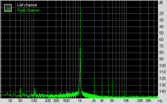
The first spectrum enclosed shows the osc. output as delivered, the distortion having been minimized by the trimmer in the AGC circuit. Since the best result was obtained with the trimmer in an end position, there may still be potential for further distortion reduction here.
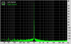
The second spectrum was obtained with 2xLM4562 instead of the original 2x5532.
While the 2nd remained unchanged, the higher harmonics were considerably reduced.
Replacing the TL071 in the AGC control circuit by an OPA134A resulted in a considerably reduced 3rd (-9dB down), whereas the others remained unchanged.
Note that the measurements were performed with the oscillator on the bench, but in the darkness because the lighting in my room produced some nasty artifacts.
So it seems that there is a potential for further improvements here. For example, the two 0.047uF/100V capacitors are of unknown type and origin, the 2SK70-GR FET is marked as K70-GR but who knows whether it is genuine, etc.
Bar the 2nd harmonic, this oscillator is otherwise possibly already as good as the one in my MOTU audio interface.
The next step will be a comparison with the Victor's oscillator, for which I must first build a proper power supply.
Regards,
Braca
Well I bought two of these for the fun of it, and here are my first experiences.Here's an inexpensive fixed frequency (1kHz) oscillator which can be adjusted to -105dB THD.
Assembled Low Distortion Audio Range Oscillator 1KHz Sine Wave Signal Generators
Powered with a 2x12.5V power supply the oscillator puts out 6.75Vrms @ 1kHz. Since this level is too high for the audio interface I'm using for measurements (MOTU Audio Express), I placed a 2x5K voltage divider at the output and made all measuremens with half the nominal output voltage, producing a nominal level of -10dB in the spectra.
The measurements were performed in the 24/96 mode using the RMA software. Since the latter expects a loopback configuration for THD measurements, I only used it to acquire the data and processed those subsequently with the RMA spectrum analyzer. The freq. resolution in all spectra enclosed is 0.73Hz, Hann window, and FFT overlap is 75%.
The first spectrum enclosed shows the osc. output as delivered, the distortion having been minimized by the trimmer in the AGC circuit. Since the best result was obtained with the trimmer in an end position, there may still be potential for further distortion reduction here.
The second spectrum was obtained with 2xLM4562 instead of the original 2x5532.
While the 2nd remained unchanged, the higher harmonics were considerably reduced.
Replacing the TL071 in the AGC control circuit by an OPA134A resulted in a considerably reduced 3rd (-9dB down), whereas the others remained unchanged.
Note that the measurements were performed with the oscillator on the bench, but in the darkness because the lighting in my room produced some nasty artifacts.
So it seems that there is a potential for further improvements here. For example, the two 0.047uF/100V capacitors are of unknown type and origin, the 2SK70-GR FET is marked as K70-GR but who knows whether it is genuine, etc.
Bar the 2nd harmonic, this oscillator is otherwise possibly already as good as the one in my MOTU audio interface.
The next step will be a comparison with the Victor's oscillator, for which I must first build a proper power supply.
Regards,
Braca
Attachments

The next step will be a comparison with the Victor's oscillator, for which I must first build a proper power supply.
Regards,
Braca
That's interesting, but first you need to know your measurement system possibilities. As I know, no one soundcard, or any ADC system can properly measure harmonics under -130dB. Measurements under -130dB can be made adequately only via twin T notch filter (passive filter is preferred in my opinion). Every step in this way must be done very carefully.
Victor.
Yes, I'm well aware of the fact that these measurements are not absolute.
My interest in this exercise was to see relative changes in the spectra as changes are made to the oscillator. Since nothing else was changed in the setup, the relative changes observed should be valid.
As a matter of fact I've already built a twin T notch filter for your oscillator, it's only waiting to be fine-tuned.
Regards,
Braca
Yes, I'm well aware of the fact that these measurements are not absolute.
My interest in this exercise was to see relative changes in the spectra as changes are made to the oscillator. Since nothing else was changed in the setup, the relative changes observed should be valid.
As a matter of fact I've already built a twin T notch filter for your oscillator, it's only waiting to be fine-tuned.
Regards,
Braca
Yes, we can see relative changes, but sometimes we can go to the wrong conclusions. Sometimes harmonics from different parts of the system play with each other, especially the second harmonic.
In my own way, first step, when I use unknown ADC, is reducing the input signal from the reliable sine source for the ADC to the point, when harmonics become invisible. Also needs to check, if no artifacts at lower levels. If all is ok, then this would be the max input (0dB) for this ADC. Next step is to use twin T notch and the buffer amplifier at the ADC input. The quality of the twin T filter parts, is very the important thing. Only metal film resistors and perfect polypropylene or polystyrene capacitors (or maybe rare other types) can be used. I can recommend Wima FKP2 or polystyrenes from LCR.
Regards.
Have you tried C0G capacitors?
- Home
- Design & Build
- Equipment & Tools
- Low-distortion Audio-range Oscillator