Hi George, I'm still digesting this information (I'm a bit thick sometimes when it comes to electrical circuit theory)
Me too 😀 (I mean that I am digesting the information too AND that I am thick too when it comes to electrical circuit theory) 😉
There are two hypotheses made, remaining to be substantiated later by further measurements.
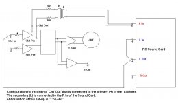
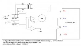
One is that the LF roll off is affected by the (reflected to the) primary impedance and the other is that the 50Hz main’s noise is picked up by the x-formers themselves and not from the interconnects.
For now, some more data
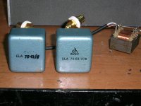
It is from two x-formers that I have salvaged from some recording desk modules I found on the street by the garbage container.
The x-formers are made in 1968 by AUSO. (may be a subsidiary of Siemens in Italy?)
They are shielded externally and incorporate an electrostatic shield btn primary and secondary.
Attachments
Hi George by the reflected impedance, do you mean the inherent impedance of the secondary winding or the impedance of the load attached to that winding?
Tony.
Tony.
Hi George by the reflected impedance, do you mean the inherent impedance of the secondary winding or the impedance of the load attached to that winding?
Tony.
Tony
Reflected voltage, current, and impedance across a transformer - Semiconductor Technical Support at Texas Instruments
The voltage from the secondary side multiplied by the turns ratio is equal to the reflected voltage on the primary side. The current on the secondary side divided by the turns ratio is equal to the reflected current on the primary side. The impedance on the secondary side divided by the square of the turns ratio is equal to the reflected impedance on the primary side. The turns ratio is equal to the number of primary turns divided by the number of secondary turns of the transformer.
reflected impedance: Definition from Answers.com
I hope that these help. If not, ask again🙂
Sorry for the delay.I was distracted.
Radio was transmitting Enrico Caruso in “ il Pagliacci ”. Live recording from 1904 !
Listening to such a tenor, turns the quest for Hi Fidelity sound into a meaningless wandering.


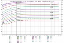
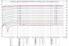
Here is data for AUSO ELA 75-12/8 x-former
Attachments


Oops
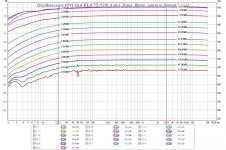
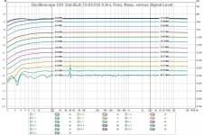
I forgot to normalise the numbering on the dB vertical axis.
Here are the same diagrams with the dB axis starting from 0dB on top.
Regards
George
I forgot to normalise the numbering on the dB vertical axis.
Here are the same diagrams with the dB axis starting from 0dB on top.
Regards
George
Attachments
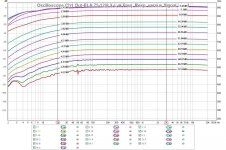
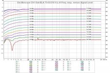
Hi George, very impressive results with the ELA 75-03/218! I think this confirms your suspicion about the transformers themselves picking up the 50Hz as well 🙂
Do you know the specs of each of the ELA transformers?? Nice find!!
I understand the reflected impedance now (I think) with a turns ratio of 1:1 the primary should see the same impedance as the secondary, ie the input impedance of the sound card... So I'm still at a bit of a loss as to how this causes the freq response to vary with drive level 🙂
Tony.
Hi George, very impressive results with the ELA 75-03/218! I think this confirms your suspicion about the transformers themselves picking up the 50Hz as well
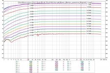
Tony, both of these AUSOs perform excellent in terms of main’s noise immunity.
And yes, this confirms my suspicion.
All plots shown are with the inner electrostatic shield and the outer metal screen floating, that is, not connected to Sound card’s common (call it “ground”).
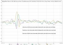
Here you’ll see (att.1) a magnified view of the lowest signal curve. The difference btn. the 3 different configurations is I would say minimal.
I suspected that the good main’s rejection with everything floating was due to some symmetric physical construction of the x-formers innards.
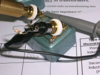
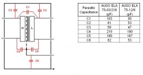
I can not visibly see what’s the internal construction on these x-formers but the capacitance measurements (att.2) can provide some hints.
They are not torroidal. C2=C3 and C4=C5 (on each x-former) if they were .
They are not C-core with bobbins on opposite core legs. There wouldn’t be a need for inner electrostatic shield and C1 would be quite smaller.
The remaining case is that the two coils are wound over the same core leg.
Core may be either E-I or E-E shape.
They are not wound bifilar. C1 is low.
C2 is not equal to C3. Thus the two coils may be not wound on two side by side bobbins on the same leg but on one bobbin. C2 is larger than C3, which shows that H coil is closer to the outer metal screen and L coil is the inner one (this may not be so, if magnetic core is in electrical contact with the outer metal screen.)
[C2-C3] is not large, indicating that coil thickness is small (few wire layers)
C4 is larger than C5, suggesting that inner electrostatic shield is physically closer to H coil (primary) than to L coil (secondary).
Do you know the specs of each of the ELA transformers??
In att.3 you will see some measurements for these, tabulated with my other x-formers for comparison.
From these measurements, the leakage inductance measured from the primary side is very different from the leakage inductance measured from the secondary side. This suggests that L (secondary) is wound over the H(primary) on the same bobbin.
A brief look at the Inductance/DC Resistance measurements, leads to the hypothesis that the core material of these x-formers should have a much higher permeability than mine’s.
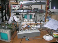
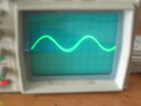
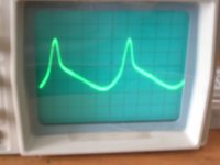
This is good at first sight but I’ve observed with the scope highly distorted waveforms at frequencies at and below 50Hz, something that does not show in the previously attached curves (they were not meant to show distortion, only Freq.Resp).
Therefore their superiority in LF response compared to the experimental ones is under the lup.
The experimentals do "down slope" earlier, but start distorting lower and more gracefully (with the same 1Vrms applied on all primaries)
Attached are some bad quality
 screenshots.
Att.4&5 are Primary current waveforms (50R series resistor).
Att. 6&7 are resulting Secondary (//10k) voltage waveforms.
All are at freq. of 20Hz. The distorted ones are from one of AUSOs, the almost sinusoidal are from the bifilar. Sorry for not being precise on this, but now I can’t find my notes with the specific details.😡
Anyway, this behaviour will be investigated further later on, as it seems to me that this too is one of the reflected impedance effects, which is not such a simple animal as I initially ***umed. I have gathered some data but they need to be organized to be shown. So, this for now🙂
Regards
George
Attachments
-
 1 magn view for shielding effectiveness.jpg108.5 KB · Views: 96
 -
 2 ELA Capacitances.JPG39.8 KB · Views: 106
 -
 3 Manual Measurements.JPG79.1 KB · Views: 94
 -
 6 Picture 011.jpg384.5 KB · Views: 100
 -
 5 Picture 022.jpg446.5 KB · Views: 93
 -
 4 Picture 014.jpg417.7 KB · Views: 97
 -
 7 Picture 008.jpg354.9 KB · Views: 93
Last edited:
Anyway, this behaviour will be investigated further later on, as it seems to me that this too is one of the reflected impedance effects, which is not such a simple animal as I initially ***umed.
I noticed the 3 asterisks being placed by the site’s robot that automatically censors the text.
What happened?
I wrote the word “assumed” and no asterisks but I marked the 3 first letters as bold text.
It seems thus that the censoring algorithm interpreted these 3 letters as a separate forbidden word and marked it as such.
Why do I follow-up on this?
Because the “dump” algorithm unintentionally managed to transmit exactly the same message that once in my ex professional career, a wise British auditor had warned me of:
“If you ever allow yourself to assume something without overseeing it or testing it yourself , you become what the 3 first letters of this verb mean”
Although I "got" this harsh message immediately, it took me 2-3 incidents to make me adopt it as a SOP *
Regards
George
*SOP="Standard Operating Procedure" , thanks to Scott Wurser 😉
http://www.diyaudio.com/forums/analog-line-level/146693-john-curls-blowtorch-preamplifier-part-ii-1278.html#post2600371
Last edited:
Hi George, I am starting to understand why it is that "audio quality" transformers are so expensive! It looks like there are many tradeoffs, and you have to pick your tradeoffs wisely. Perhaps there is a holy grail, but I suspect that it is quite a quest to find it 😀
An old boss of mine once told me. " Never assume, if you do it makes an *** out of u and me" 🙂
Tony.
An old boss of mine once told me. " Never assume, if you do it makes an *** out of u and me" 🙂
Tony.
Last edited:
Hi Tony.
I saw your post just now that I was trying to post mine.
I hope you are doing well.
Now my post
This thread was started in an attempt to help Tony with his noise measurements on PSU.
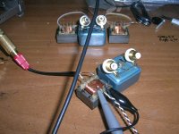
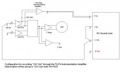
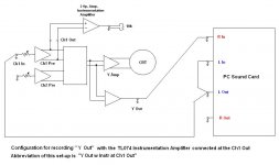
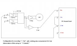
I started with the idea of using a x-former as an easy implementation of a “differential to single ended” adaptor for bringing out to a sound card what one can probe with an oscilloscope.
I think that it is better to halt the long masochistic investigation on (not so easy as found out implementation of) x-former solution for a while, in order to show to frustrated 😀 Tony a not so difficult alternative.
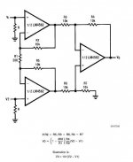
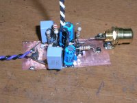
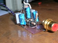
It is an implementation of the classic 3 op.amp. instrumentation amplifier (att.1).
After some basic level simulation trials, I built it using a quad op.amp TL074.
The 6db/oct LF roll-off is due to the combination of Input cap and input shunt resistor.
The cap is needed to block the DC at the input. The input shunt resistor is for referencing each input to system ground. Increasing this resistor’s value I can lower the LF roll-off freq. without increasing the cap value (and size), but I think that I will increase the noise as well. So, 1uF and 47k seems a good compromise.
The HF roll-off is due to gain-bandwidth product of the 2 gain blocks. It goes up as the gain goes down.
R2 to R7 are 10k 5% hand matched to +/-2 Ohm.
R1 sets the gain.
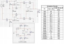
In att.2, you’ll see a table with R1 value/Gain/HF –3db roll off freq.
These are results from simulation using a virtual op. amp model.
After I built it, I tested it with 3 different R1. Results:
R1=200 Ohm
Gain=38.9dB
Bandwidth (-6dB): 2.5Hz-58kHz
Overload (with +/- 15Vdc PSU and 10k output load)
Output: 9.781Vrms
Input: 104.9mVrms
R1=2k166
Gain=20.1dB
Bandwidth (-6dB): 2.5Hz-660kHz
Output: 9.48Vrms
Input: 920mVrms
R1=7k332
Gain=10.74dB
Bandwidth (-6dB): 2.5Hz->2MHz (~2.1MHz)
Output: 7Vrms
Input: 2.5Vrms
The 4th unused op. amp of TL074 can be used as a voltage comparator lighting up a LED when the output reaches 1Vrms (limit of most sound card input). I will figure out how to do it later.
I saw your post just now that I was trying to post mine.
I hope you are doing well.
Now my post
This thread was started in an attempt to help Tony with his noise measurements on PSU.
I started with the idea of using a x-former as an easy implementation of a “differential to single ended” adaptor for bringing out to a sound card what one can probe with an oscilloscope.
I think that it is better to halt the long masochistic investigation on (not so easy as found out implementation of) x-former solution for a while, in order to show to frustrated 😀 Tony a not so difficult alternative.
It is an implementation of the classic 3 op.amp. instrumentation amplifier (att.1).
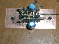
After some basic level simulation trials, I built it using a quad op.amp TL074.
The 6db/oct LF roll-off is due to the combination of Input cap and input shunt resistor.
The cap is needed to block the DC at the input. The input shunt resistor is for referencing each input to system ground. Increasing this resistor’s value I can lower the LF roll-off freq. without increasing the cap value (and size), but I think that I will increase the noise as well. So, 1uF and 47k seems a good compromise.
The HF roll-off is due to gain-bandwidth product of the 2 gain blocks. It goes up as the gain goes down.
R2 to R7 are 10k 5% hand matched to +/-2 Ohm.
R1 sets the gain.
In att.2, you’ll see a table with R1 value/Gain/HF –3db roll off freq.
These are results from simulation using a virtual op. amp model.
After I built it, I tested it with 3 different R1. Results:
R1=200 Ohm
Gain=38.9dB
Bandwidth (-6dB): 2.5Hz-58kHz
Overload (with +/- 15Vdc PSU and 10k output load)
Output: 9.781Vrms
Input: 104.9mVrms
R1=2k166
Gain=20.1dB
Bandwidth (-6dB): 2.5Hz-660kHz
Output: 9.48Vrms
Input: 920mVrms
R1=7k332
Gain=10.74dB
Bandwidth (-6dB): 2.5Hz->2MHz (~2.1MHz)
Output: 7Vrms
Input: 2.5Vrms
The 4th unused op. amp of TL074 can be used as a voltage comparator lighting up a LED when the output reaches 1Vrms (limit of most sound card input). I will figure out how to do it later.
Attachments
Last edited:
VERY nice P2P work George! I like the use of the copper!! I have a TL074 in my junk box too!
I'm doing ok. We had a long weekend (queens birthday holiday) but I spent almost the entire time fixing my father-in-law's pc that had been wiped by a virus, so I didn't get the chance to try putting my preamp into a proper sheilded box.
Don't worry about my suffering, I'm worried about yours!!! 😀
Tony.
Good to hear from you.
We are doing OK here * too.
My Old Man passed away peacefully last Tuesday at 88 (heart attack).
It was 5 minutes I had finished some impedance sweeps ** that I received the call from my mother to go there.
He was sitting in his armchair.
I closed his beloved eyes.
I couldn’t hope for a better ending.
*Relatively speaking
**That’s why I will always remember this thread.🙂
Attachments

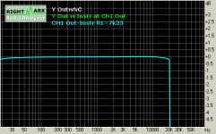
This little bug performs well.
With R1=7k332 the signal from it’s output has the same amplitude (it is actually 0.13db higher) with the “Y-Out” of my oscilloscope.
Here you see some RMAA comparison plots.
Actual signal output on these measurements is 1.113Vrms (–1.3 dB of my sound card’s 0dB)
4th att.:frequency response
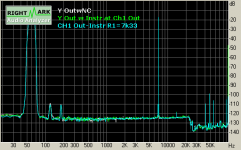
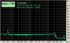
5th att.:Intermodulation distortion (60Hz & 7kHz)
6th att.: Noise
7th att.: Total harmonic distortion
With R1=7k332 the signal from it’s output has the same amplitude (it is actually 0.13db higher) with the “Y-Out” of my oscilloscope.
Here you see some RMAA comparison plots.
Actual signal output on these measurements is 1.113Vrms (–1.3 dB of my sound card’s 0dB)
4th att.:frequency response
5th att.:Intermodulation distortion (60Hz & 7kHz)
6th att.: Noise
7th att.: Total harmonic distortion
Attachments

Good to hear from you.
We are doing OK here * too.
My Old Man passed away peacefully last Tuesday at 88 (heart attack).
It was 5 minutes I had finished some impedance sweeps ** that I received the call from my mother to go there.
He was sitting in his armchair.
I closed his beloved eyes.
I couldn’t hope for a better ending.
*Relatively speaking
**That’s why I will always remember this thread.🙂
George I am so sad to hear that 🙁 It is a lovely photo!
Take it easy. my thoughts are with you my friend!
Tony.
Thank You Tony. I know that you mean it.
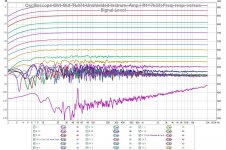
Now, let's put some numbers in the last diagram.
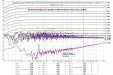
First att. is the Sound Card's Input signal level in dBs relative to 0 dB of the Card.
The 0dB for my card is 1.286Vrms.
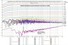
Second att. is the Sound Card's Input signal level in mVrms
I think that you would agree with me that Curves C1 to C9 are pretty descent
Now, let's put some numbers in the last diagram.
First att. is the Sound Card's Input signal level in dBs relative to 0 dB of the Card.
The 0dB for my card is 1.286Vrms.
Second att. is the Sound Card's Input signal level in mVrms
I think that you would agree with me that Curves C1 to C9 are pretty descent
Attachments
Now we can have a look at how the output of this circuit is related to what is probed with the oscilloscope's probe.
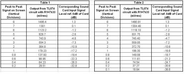
On the first att. You’ll see two tables.
Table 1 relates the peak to peak signal on the screen of the oscilloscope in vertical divisions with the output of the TL074 circuit with R1=7k33, in mVrms. On this table the mVrms measurements were taken through a single measurement for each screen’s 1kHz sinusoidal signal.
In an attempt to minimize the error from the visual uncertainty reading the screen height of the sinusoid, as well as the error due to the vertical linearity of the oscilloscope, I made 5 measurements for each screen signal, averaged them, then I averaged the mean of the 5 upper higher (8 divisions up to 5 divisions) signals.
Next, I applied this final mean to the whole table. Results are on Table 2.
From these results you can see that even the smallest readable screen signal results in a signal amplitude at the input of the card which is at or higher from the “clean” curve C7 on the diagrams of the previous post, which I attach again here for convenience (second att.).
These are good news (at last 🙄)
Now let’s see how low an amplitude should the probed signal have, for to fall within the reliable range of curves C2 to C7.
This depends on the sensitivity settings of oscilloscope Ch1 Input and the probe used.
With my oscilloscope, using a sensitivity setting of 1mV/div and using a 1:1 probe, a sinusoidal signal of 0.63mVrms (the weakest signal from my modified Signal Generator) results in 1.8 vertical divisions pp signal on the screen. This translates to 335mVrms at the card’s Input. (Even probing the same 0.63mVrms with a 10:1 probe, the signal would be 33mVrms at the card’s input, still above C7 curve.)
In theory at least 😀, with a sensitivity setting of 1mV/div and using a 1:1 probe (which results in a combined 53dB amplification from probed signal to card’s input) , to reach curve C9, the probed signal has to be 9uVrms !!!
At such low level signals - as you already have found out – even the probe’s ground clip length can ruin the measurement, not to mention the ground loop issue and the RF pollution. 😡
Regards
George
Attachments

Last edited:
Hi George, I've just now put this photo up on Flickr Eternal Peace | Flickr - Photo Sharing!. It has made me a bit teary "which is somewhat embarassing as I am on the train 😀"
I'll read your responses a bit later when feeling a bit more composed 🙂
cheers,
Tony.
I'll read your responses a bit later when feeling a bit more composed 🙂
cheers,
Tony.
Thank You Tony.
I appreciate.
If it will ever happen to meet in person, we will taste a few of these reds together.
This photo makes me a bit teary too.
Elder people evidently turn into babies and this brings back memories from my parent’s soothing and tender when we were children and they were taking care of us during our small age frequent illnesses.
You take love, you give back love. That’s how I feel it. But this is rational.
Giving love with free will, as they did, although irrational, was (and is) soul soothing. This is what we might learn (by observation) from the elder.
Last edited:
Hi George, very good results indeed!
When I was first simulating I was looking at stuff this small and optimising to eliminate, little did I know how far from that I would be able to measure with my scope (I didn't even have a scope when I started).
The disappointment was great when I connected my scope and found that with it's maximum resolution of 2mV / div that all sorts of rf and other noise pickup made my scope trace at low frequencies quite thick and impossible to distinguish the low levels I was interested in from the wideband noise.
Then I came across your CRCRC experiment thread, and your method was a revelation 😀
I'd once again like to thank you for your efforts in doing this, it is greatly appreciated! 🙂
Tony.
In theory at least , with a sensitivity setting of 1mV/div and using a 1:1 probe (which results in a combined 53dB amplification from probed signal to card’s input) , to reach curve C9, the probed signal has to be 9uVrms !!!
When I was first simulating I was looking at stuff this small and optimising to eliminate, little did I know how far from that I would be able to measure with my scope (I didn't even have a scope when I started).
The disappointment was great when I connected my scope and found that with it's maximum resolution of 2mV / div that all sorts of rf and other noise pickup made my scope trace at low frequencies quite thick and impossible to distinguish the low levels I was interested in from the wideband noise.
Then I came across your CRCRC experiment thread, and your method was a revelation 😀
I'd once again like to thank you for your efforts in doing this, it is greatly appreciated! 🙂
Tony.
- Status
- Not open for further replies.
- Home
- Design & Build
- Equipment & Tools
- Implementing a “Y Out” on an Oscilloscope