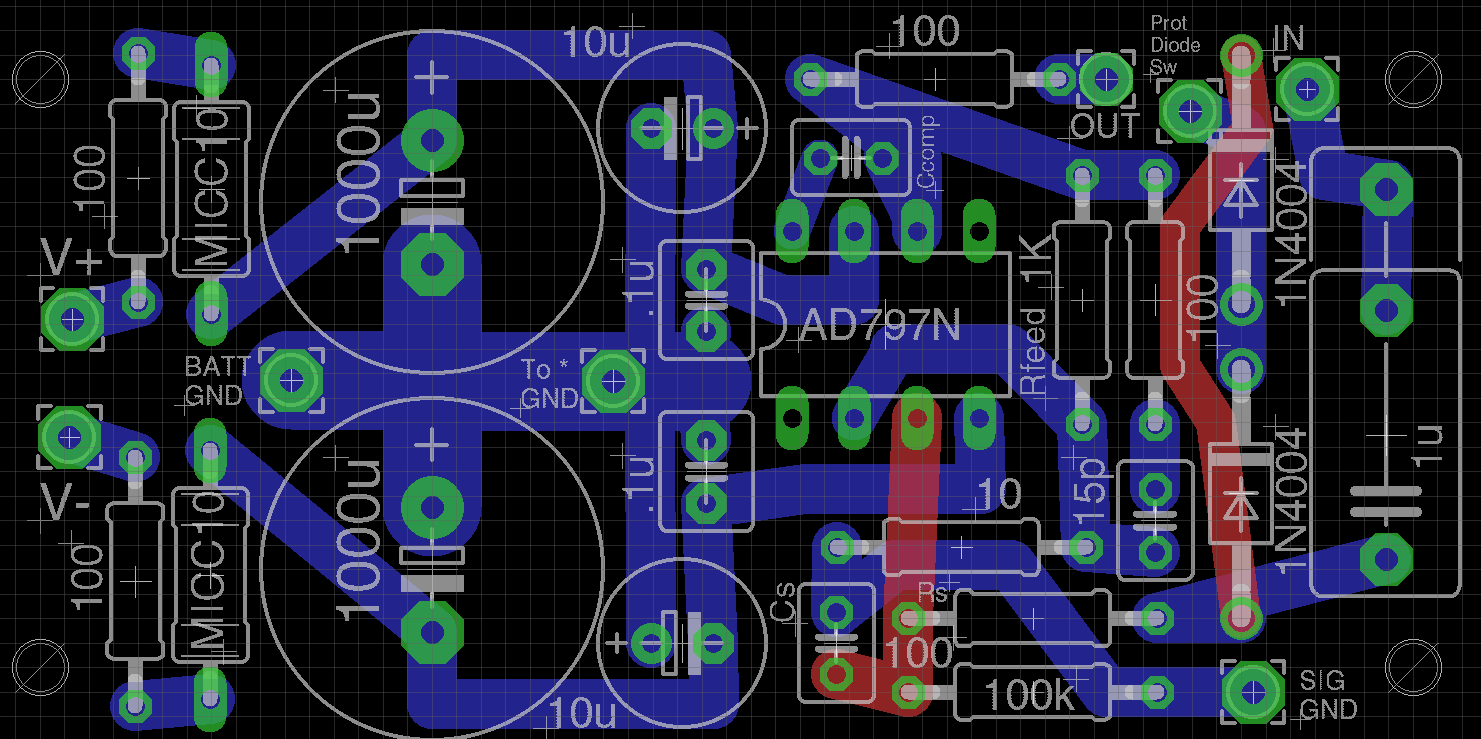
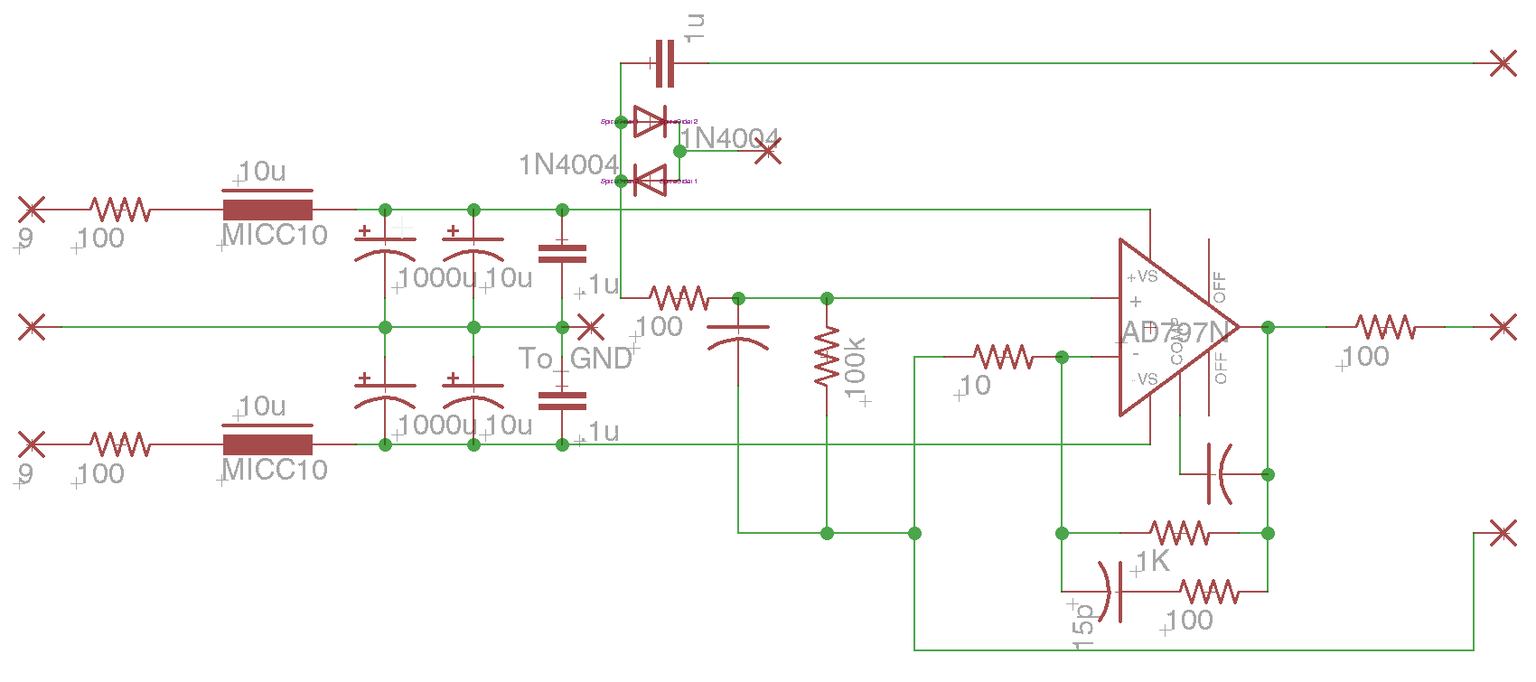
Edit: With input coupling cap.
If I put a pair of back-to-back diodes on the input, to protect it when I measure power supplies with 85V rails, will that introduce noise on the input? I guess it would, so I suppose I couuld make that switchable.
EDIT: I guess the input protection diodes would not introduce noise, as there would be no DC current flowing.
Last edited:
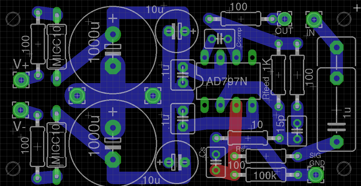
A couple of observations. I see you are using Eagle for PCB layout. You can select different trace behaviors when using the trace tool. Looks like you are in the arbitrary angle mode. You can clean up the odd angles by using the 45 degree mode (so all bends in the traces are at 45 degrees instead of random. Makes for a cleaner layout.
You can also use polygons to create larger trace areas. For example, in your layout above, you appear to be using some super fat traces to connect the grounds of the caps. You could just create a polygon in the appropriate layer (in your case here, bottom trace - blue). Name the signal in the schematic (e.g Ground), and then name the polygon the same name.
Since you are after low noise, you might also consider using a ground plane. You can do that the same way, by covering one side of the board with a single polygon, and naming it GND. Then use the "rats-nest" tool (looks like a little star.. lower left corner, next to the auto-route icon). That will connect any part that is connected to ground to the ground plane. (In my layout for the matcher, I used this for the ground plane on the top side of the board). The Ratsnest tool will automatically make room for other traces on that layer. So, for example you could do a top side ground plane on the above board, and the two top side traces would stay there, but the tool would create a void in the ground plane where the trace is.
Make sure you have enough setback for screw heads around the holes.
Are you trying to keep the battery ground and signal ground separate?
Why are you using such fat traces? The currents here can't be that high.
Scott
Thanks Scott,
Yes, I like arbitrary mode. I'm after compactness more than straight lines.
Fat traces stand up to re-working better, and I'm also just taking up available space. Yes, currents are miniscule!
I don't care for pouring a huge ground plane. I can better visualize where the currents are going if I draw the traces. Yes, I'm keeping battery and signal ground separate, as well as separate path for the charging currents, as tiny as they must be. They will star-ground at the input/output jacks.
I'm not sure if pouring a big ground plane for shielding would actually help. I've read that this is possibly a bad practice, with parasitic capacitances everywhere. It probably wouldn't matter for this circuit. But there are no transformers in the box, so there's not much to shield from.
I've started a new thread for the discussion about the low-noise instrumentation preamplifier.
http://www.diyaudio.com/forums/solid-state/307137-black-box-instrumentation-preamplifier.html
http://www.diyaudio.com/forums/solid-state/307137-black-box-instrumentation-preamplifier.html
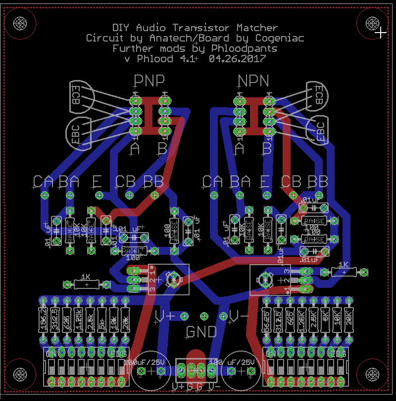
Here's my latest fork of the matcher board project, with the 8-bit current selection, and a DIP-socket to space the DUTs so you can use a fan.
And the Eagle files...
https://www.dropbox.com/s/o3ccaw2guttgivv/MATCHER-4.zip?dl=0
And the Eagle files...
https://www.dropbox.com/s/o3ccaw2guttgivv/MATCHER-4.zip?dl=0
I found a schematic in post1.
It shows zero resistance in the emitter leads to the CCS. That's OK, since many LTP implementations have zero emitter resistance.
It shows 100r as the collector resistor. These are used to measure the Collector current.
It shows 10k as the base feed resistor. These can be used to check the hFE at each of your selected Ic set by the CCS adjuster.
I cannot see a setting to allow the base resistor to be shorted out.
Is that the way you have implemented your "matcher"?
I ask because the 10k base resistor will lead to a change/difference in Vbe actually applied to each transistor.
If Ic and/or hFE are slightly different between the DUT and REF in the matching jig, the base resistor will drop a different voltage with the result that the two devices are being subjected to a different control Vbe voltage while you take the voltages being used to assess the match.
Hi Andrew,
The 10K base resistors are intentional and implemented on my matchers with 0.1 % resistors. They are there so that you can measure the beta of the pair and to also double check that the betas are the same in case you start running into poor matches. You're supposed to presort the transistors using whatever you are comfortable with, then from those sub-groups you test for exact matches (or close enough matches). You will find that in a batch of transistors, your emitter - base drops are very close, as they would be. You'll also discover just how poor the method you were using to match parts was. In my experience, the comparison will really underscore the need to match using the jig. Keep in mind that you can call pairs a match a bit more loosely allowing for so many mV across the collectors. The intent being exact matches if and when desired, and very good matches for normal stuff. These matches will be much closer than the meter hFE method.
Commercial matched parts in one package average between 2 and 5 %. Matches made with the jig will be much closer than what you can buy pre-matched. Its not hard to create a population of sub 1% matched pairs. Now, what does that say about how close the degeneration resistors have to be to maintain your hard work? The same applies to commercial dual devices (or quads) that have standard 5% degeneration resistors. How many folks out there will pay extra for close matches then turn around and use 5% carbon film resistors for the degeneration application?
-Chris
So, I've got yet another revision of the matcher board here. I've made a space on the board to mount a standard 80mm computer cooling fan, and I've made the layout a bit more symmetrical, for even airflow over the DUTs and resistors. If anyone is interested in the Eagle PCB files, or Gerbers, let me know and I'll post them.
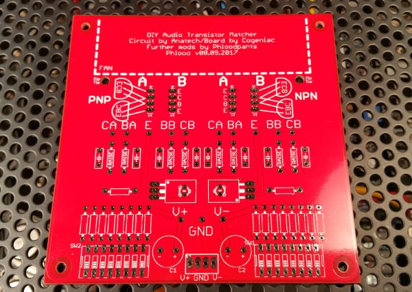
...but I think this is maybe not the last revison!
I'm thinking maybe it also needs adjustable collector resistances.
I've found it hard to match devices using the 100R collector resistors. I was getting better matches with my old matching jig, which used 1K collector resistors, and a similar current-source setup. The matches from this old jig have always been excellent.
So, please correct me if I'm wrong, but I think this is the problem with the 100R collector resistors:
When matching a pair of transistors for 1ma of currrent (2ma current source) A 100R collector resistor has only about 100mV across it, dissipating about 100µW. The voltage drop across these resistors is what we're interested in. They need to be very precisely matched, of course. But by dropping such a low voltage across it, we become very sensitive to changes in temperature. Also, small parasitic resistances such as the circuit board traces, mechanical contacts in the DUT sockets, etc, ...are significant compared to the 100R collector resistance.
So, by simply using a 1K collector resistor, the voltage drop across the collector resistor multiplies by 10x to about 1V. Current in the resistor also multiplies by 10X to 1mW. Despite the greater self-heating of the resistor, it seems to produce more stable results.
So, it seems to me there must be some kind of sweet spot. The more you drop voltage across the resistor, the more it will self-heat. But as long as you use good low-TCR resistors, maybe not so much of a problem.
So, is there an optimum voltage drop across the collector resistor we're looking for? 1/2 supply voltage maybe? Are we looking to minimize VCE and thus power dissipated in the DUTs? I assume that resistors change less with temperature than transistors, but I suppose that depends on the circuit.
Hi Phloodpants,
The 100R0 resistors (I used 0.1%) seem to work great, but your meter should be used as a null device. Hang it between the collectors and measure the difference. The lower the number, the better your match will be.
The reason I went with 100R is because I didn't want the collector voltages to vary much between the transistors. That would throw a whole new wrinkle into trying to match devices. Your 12 V power supplies are fine, anything around the 10 V mark C-E voltage will work well and can compare to the test voltage the semiconductor companies tend to use.
So basically, use your meter as a null indicator between the collectors. You could even use a centre tune meter for this. It would have to be a sensitive one. I might even give that a try. Your good matches will be measuring less than 1 mV. So that means you need a meter that has good sensitivity in the mV range. This has the advantage of being less important for calibration of the meter as the measurement is a retaliative one. Also you are only taking one reading and there isn't any math involved.
Best, Chris
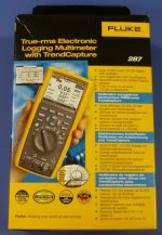
Thanks, yes I am using a Fluke 287 between collectors.
Honest question, what is the concern about VCE? That the beta changes with VCE? With a 100R collector resistor, the VCE is 12.6V, and with the 1K resistor it's 11.6V. Is that 1V enough to throw the beta value off? I can't seem to find any datasheets with a graph for VCE vs. beta.
Honest question, what is the concern about VCE? That the beta changes with VCE? With a 100R collector resistor, the VCE is 12.6V, and with the 1K resistor it's 11.6V. Is that 1V enough to throw the beta value off? I can't seem to find any datasheets with a graph for VCE vs. beta.
Last edited:
the collector resistors that are used to measure the currents must be matched very accurately. I aim for better than 0.1% (a 2000 count DMM can get you to matching of ~0.05%, a 20000count DMM can get you to better than 0.01%)...but I think this is maybe not the last revison!
I'm thinking maybe it also needs adjustable collector resistances.
I've found it hard to match devices using the 100R collector resistors. I was getting better matches with my old matching jig, which used 1K collector resistors, and a similar current-source setup. The matches from this old jig have always been excellent.
So, please correct me if I'm wrong, but I think this is the problem with the 100R collector resistors:
When matching a pair of transistors for 1ma of currrent (2ma current source) A 100R collector resistor has only about 100mV across it, dissipating about 100µW. The voltage drop across these resistors is what we're interested in. They need to be very precisely matched, of course. But by dropping such a low voltage across it, we become very sensitive to changes in temperature. Also, small parasitic resistances such as the circuit board traces, mechanical contacts in the DUT sockets, etc, ...are significant compared to the 100R collector resistance.
So, by simply using a 1K collector resistor, the voltage drop across the collector resistor multiplies by 10x to about 1V. Current in the resistor also multiplies by 10X to 1mW. Despite the greater self-heating of the resistor, it seems to produce more stable results.
So, it seems to me there must be some kind of sweet spot. The more you drop voltage across the resistor, the more it will self-heat. But as long as you use good low-TCR resistors, maybe not so much of a problem.
So, is there an optimum voltage drop across the collector resistor we're looking for? 1/2 supply voltage maybe? Are we looking to minimize VCE and thus power dissipated in the DUTs? I assume that resistors change less with temperature than transistors, but I suppose that depends on the circuit.
100r when used for 1mA of collector current gives 100.0mVdc
Any DMM set to 199.9mVdc will measure your two voltages with a resolution of 0.1mVdc. You can also measure the differential voltage between the collectors as a final check for matching.
I see nothing wrong, or inadequate, with using 100.0mVdc as the current measuring value.but your meter should be used as a null device. Hang it between the collectors and measure the difference (attribution) from post 52 by Anatech.
I agree that your measuring instruments do need to be better than the matching tolerance you are aiming for.
If you had <0.5mA for Ic, then I would go to a higher value of collector resistor, maybe 1k +-0.05% (that's the 0.1% range of tolerance again).
But, have you inserted a base resistor for each half of the testing jig? That will give an error unless you separately measure the actual Vbe of each half.
The base resistor must be low, or zero when matching. The two devices need to have the same Vbe applied when making the comparison for Ic.
The base resistor is only required to determine the hFE, NOT for matching. Make it switchable.
Last edited:
Many datasheets show the variation of Ic vs VceThanks, yes I am using a Fluke 287 between collectors.
Honest question, what is the concern about VCE? That the beta changes with VCE? With a 100R collector resistor, the VCE is 12.6V, and with the 1K resistor it's 11.6V. Is that 1V enough to throw the beta value off? I can't seem to find any datasheets with a graph for VCE vs. beta.
Read off the Ic & Ib and you have hFE.
Hi Andrew,
-Chris
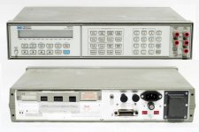
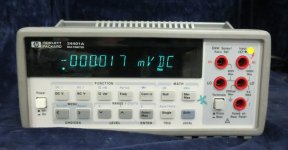
Unfortunately, not true. In resistance mode you are using an internal current source that can drift (and they do). The meters I use have a basic DC accuracy of 0.05%. Those are my handheld HP / Agilent / Keysight meters. Resistance accuracy is substantially less and depends on the range and reading. To match these resistors, I typically use my HP 3457A, or my 34401A. They are used in 6 (1/2) digit mode with long averaging and a 3 Hz AC filter engaged. I buy 0.1% resistors and match within that group. I haven't worked out the error budget on those, but I wouldn't want to claim extreme accuracy. The leads are copper, as are the clips. I was in the field of Metrology professionally for a little while.I aim for better than 0.1% (a 2000 count DMM can get you to matching of ~0.05%, a 20000count DMM can get you to better than 0.01%)
You're in for a nasty surprise. Here's a hands on project for you. Look up your meter and using the accuracy specs, work out your error uncertainty. Trust me when I say, it will not be that good. If you check some of the meters out there, the 2 LSD don't mean anything at all.Any DMM set to 199.9mVdc will measure your two voltages with a resolution of 0.1mVdc.
Yes, and that is why they are there. I'm not married to having them in circuit. But rather than a switch, use 0.1" headers and jumpers instead of a switch. Either that, or simply replace those resistors with a piece of wire. They do not affect the balance that much.But, have you inserted a base resistor for each half of the testing jig?
-Chris
Hi Phloodpants,
The 10 VDC Vc-e voltage only makes the variations on the collector voltage less important. If the variations were made larger (as in higher resistance collector loads), or your voltage were lower - say 5 VDC, you would be inviting other variables to come play at your party.
The reason most transistors are rated around 10 VDC for AC parameters is that the variations with voltage have dropped by then, and also your self generated heat is less as well. It's a compromise and if its good enough for a manufacturer, it's good enough for me.
If you won't be measuring beta, then simply short out the base resistors. There is no reason to do another spin of the PCB. As designed, mine all give me great, tight matches. I feel like there is just nit-picking going on now.
-Chris
HP 3457A Pic
Hi ya Chris,
Yes folks, I've found Anatech to usually be correct in his assessments.
If I might add the following:
It's better to pick the nits now while your at it.
Later down the road, you'll have to deal with
substantial amounts of lice to pick those nits now.
Cheers,
Hi ya Chris,
Yes folks, I've found Anatech to usually be correct in his assessments.
If I might add the following:
It's better to pick the nits now while your at it.
Later down the road, you'll have to deal with
substantial amounts of lice to pick those nits now.
Cheers,
Attachments
Last edited:
matching resistors
But, I will take up one point:
Stringing a set of resistors together in series to pass a current (giving a reasonable number of signficiant figures) and measuring the voltage drop across each resistor gives a very good method for accurate matching of resistors. This is particularly useful with lower value resistors.
I have described this series Vdrop method many times for Beginners who need help in using their instruments to give useful results.
We have already discussed many of the points you have raised and to date we have not completely agreed on the methodology................
Unfortunately, not true. In resistance mode you are using an internal current source that can drift (and they do). The meters I use have a basic DC accuracy of 0.05%. Those are my handheld HP / Agilent / Keysight meters. Resistance accuracy is substantially less and depends on the range and reading. To match these resistors, I typically use my HP 3457A, or my 34401A. They are used in 6 (1/2) digit mode with long averaging and a 3 Hz AC filter engaged. I buy 0.1% resistors and match within that group. I haven't worked out the error budget on those, but I wouldn't want to claim extreme accuracy. The leads are copper, as are the clips. I was in the field of Metrology professionally for a little while.
You're in for a nasty surprise. Here's a hands on project for you. Look up your meter and using the accuracy specs, work out your error uncertainty. Trust me when I say, it will not be that good. If you check some of the meters out there, the 2 LSD don't mean anything at all.
Yes, and that is why they are there. I'm not married to having them in circuit. But rather than a switch, use 0.1" headers and jumpers instead of a switch. Either that, or simply replace those resistors with a piece of wire. They do not affect the balance that much...........
But, I will take up one point:
Stringing a set of resistors together in series to pass a current (giving a reasonable number of signficiant figures) and measuring the voltage drop across each resistor gives a very good method for accurate matching of resistors. This is particularly useful with lower value resistors.
I have described this series Vdrop method many times for Beginners who need help in using their instruments to give useful results.
Last edited:
- Home
- Design & Build
- Equipment & Tools
- Matching transistors & measuring the results