Hall notch board V2.0 experiments - linear trimpots - part 2
..on to some QA401 measurements.
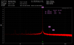
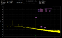
In the first two plots the red is the input from the Victor oscillator. Here I've adjusted that to be around -10.4dV, at exactly 300mV(rms) as shown at the top of the plot. The yellow is the output of the Hall notch filter, now at 119uV(rms) as shown at the the top.
This time I tried adjusting the frequency and notch depth trimpots again, while hooked to the QA401, to see if I could further reduce the notch. I couldn't! The DMM method appears to work extremely well, at least with this particular DMM (Fluke 289).
So the net result for the notch reduction is 0.119/300 = 0.000397 = -68dB, consistent with the results of the previous V1.0 boards. But the high THD and THD+N numbers at the top with the notch filter (yellow plot) are curious. I'm guessing the increase in noise floor I'm seeing below 1KHz is EMI pickup and should reduce once inside the metal box. There appears to be a bunch of harmonics out past 10KHz that are apparently contributing to the higher THD number. The THD results posted above for the previous V1.0 board with the OPA1612 were similar. I'm going to try building up one of these board just with the passive Hall notch filter (frequency pot wiper grounded) to see what that gives.
The OPA1612 chip is being used here. I'm using the low pass filter parts on the output, 49.9R series resistor and 0.022uF (50V C0G MLCC) to ground, so the corner should be around 145KHz.
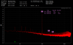
Next are some interesting screw-ups I ran into.") When I first measured the input level from the Victor board (red plot) there were a lot of harmonics. I pondered that for a bit and finally realized I had forgotten to turn on the power switch on the Hall notch board. Turned on the power and all the extra harmonics went away. But it is interesting that the load of the un-powered bipolar-input IC (OPA1612 in this case) on the output of the passive Hall notch parts would create harmonics that reflected back to the input.
When I first measured the input level from the Victor board (red plot) there were a lot of harmonics. I pondered that for a bit and finally realized I had forgotten to turn on the power switch on the Hall notch board. Turned on the power and all the extra harmonics went away. But it is interesting that the load of the un-powered bipolar-input IC (OPA1612 in this case) on the output of the passive Hall notch parts would create harmonics that reflected back to the input.
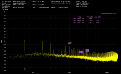
And the next is a test of adding electrolytic bypass capacitors across the batteries. I've had PCB holes for 1000uF 25V low ESR (20mR) electrolytics on all of the boards, but until now I haven't tried adding them. Never really saw any electrical advantage, given the low 0.3 ohm internal resistance of the lithium polymer batteries.
Well the final two plots show that the results of adding the electros across the batteries is pretty much disastrous. Harmonics spewed all across the spectrum. Back to just the batteries.
..on to some QA401 measurements.
In the first two plots the red is the input from the Victor oscillator. Here I've adjusted that to be around -10.4dV, at exactly 300mV(rms) as shown at the top of the plot. The yellow is the output of the Hall notch filter, now at 119uV(rms) as shown at the the top.
This time I tried adjusting the frequency and notch depth trimpots again, while hooked to the QA401, to see if I could further reduce the notch. I couldn't! The DMM method appears to work extremely well, at least with this particular DMM (Fluke 289).
So the net result for the notch reduction is 0.119/300 = 0.000397 = -68dB, consistent with the results of the previous V1.0 boards. But the high THD and THD+N numbers at the top with the notch filter (yellow plot) are curious. I'm guessing the increase in noise floor I'm seeing below 1KHz is EMI pickup and should reduce once inside the metal box. There appears to be a bunch of harmonics out past 10KHz that are apparently contributing to the higher THD number. The THD results posted above for the previous V1.0 board with the OPA1612 were similar. I'm going to try building up one of these board just with the passive Hall notch filter (frequency pot wiper grounded) to see what that gives.
The OPA1612 chip is being used here. I'm using the low pass filter parts on the output, 49.9R series resistor and 0.022uF (50V C0G MLCC) to ground, so the corner should be around 145KHz.
Next are some interesting screw-ups I ran into.
When I first measured the input level from the Victor board (red plot) there were a lot of harmonics. I pondered that for a bit and finally realized I had forgotten to turn on the power switch on the Hall notch board. Turned on the power and all the extra harmonics went away. But it is interesting that the load of the un-powered bipolar-input IC (OPA1612 in this case) on the output of the passive Hall notch parts would create harmonics that reflected back to the input.And the next is a test of adding electrolytic bypass capacitors across the batteries. I've had PCB holes for 1000uF 25V low ESR (20mR) electrolytics on all of the boards, but until now I haven't tried adding them. Never really saw any electrical advantage, given the low 0.3 ohm internal resistance of the lithium polymer batteries.
Well the final two plots show that the results of adding the electros across the batteries is pretty much disastrous. Harmonics spewed all across the spectrum. Back to just the batteries.
Attachments
Last edited:
An active twin t can have 0 attenuation at h2 depending on feedback settings. A passive twin t is different.i know I am late to the party, but how much does the Hall notch filter attenuate the 2nd harmonic compared to the active twin T, which has roughly 0.5db attenuation?
- Status
- This old topic is closed. If you want to reopen this topic, contact a moderator using the "Report Post" button.