Yesterday evening I have finally assembled my autoranger (except C6). Looking at the calibration instruction I realized that I have no wideband AC RMS voltmeter at hands (just a regular DMM) but I have a Rigol DS1054Z o-scope. I guess o-scope should be accurate enough for measuring AC levels or I really need a dedicated AC voltmeter for calibration?
Regards,
Oleg
Regards,
Oleg
Jan,
minor but you should correct the quantity also... 1 for C10, 1 for C6")
Best
JC
Oleg, yes indeed. You were also right about C1, C8 being part of the atten board, not the control board.
All corrected, thanks for the heads-up.
Jan
minor but you should correct the quantity also... 1 for C10, 1 for C6
Best
JC
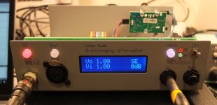
I've finished my build as well. Working nice!
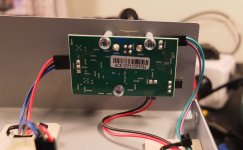
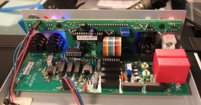
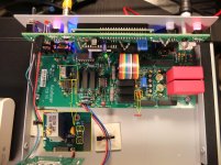
I added some pictures too with power supply wiring done with red(+)/black(gnd)/blue(-), so perhaps of help for some who's yet to do the build. Also marked the C27 where pinout needs the use of outer holes olny and the latest change of C6->360pF
I added some pictures too with power supply wiring done with red(+)/black(gnd)/blue(-), so perhaps of help for some who's yet to do the build. Also marked the C27 where pinout needs the use of outer holes olny and the latest change of C6->360pF
Attachments
Dear Jan,
the PICs arrived a week ago. Thank you very much for the generous support.
My AR is currently disassembled because I have troubles sourcing the NP0 capacitors. Now C6 has changed and I have nothing comparable in stock. At work: also nothing.
Can I test your software without C10/C6 or with 510pF?
Best regards
I used 2x180pF in parallel for C6. That was easier to find.
As far as I've understood all these caps are frequency response related. So you should be able to get the device operational also with slight differing values.
As a note - at first power on you probably will not see anything on LCD... but as documentation says this is due to contrast being way off and needing adjustment. I had missed that at first in the manual and of course got a bit worried that something is wrong...
Jan,
Is there any opportunity for us to read the current attenuation / gain level in to say our computer. Understanding that no software today would know what to do with such an input but just daydreaming for say a level sweep that the auto ranging could still be left in auto and the software adjusts as the AR does its magic!
Would the best way to do this at this stage be to tap in to the 14pin cable?
Thanks,
Chris
Dear Jan,
the PICs arrived a week ago. Thank you very much for the generous support.
My AR is currently disassembled because I have troubles sourcing the NP0 capacitors. Now C6 has changed and I have nothing comparable in stock. At work: also nothing.
Can I test your software without C10/C6 or with 510pF?
Best regards
You can test it without worrying about those caps, as they are only related to (high frequency) flatness calibration, as Ergo noted.
If you test at 1kHz they wouldn't matter.
Jan
Jan,
Is there any opportunity for us to read the current attenuation / gain level in to say our computer. Understanding that no software today would know what to do with such an input but just daydreaming for say a level sweep that the auto ranging could still be left in auto and the software adjusts as the AR does its magic!
Would the best way to do this at this stage be to tap in to the 14pin cable?
Thanks,
Chris
This is something that has been brought up in PM several times. If the AR would have a USB connection, then software could read the setting and even command a specific setting.
I am thinking about this but it's pretty involved, especially as the measurement software like ARTA etc are not set up to read it.
I think you can add a gain or atten in ARTA and other software to take care of external atten, not sure about that.
You can tap the flat cable as that has the info on the actual setting. PM me if you want to pursue this.
Jan
I think you can add a gain or atten in ARTA and other software to take care of external atten, not sure about that.
Jan
I can confirm that at least, within Arta, you can set gain or attenuation level. It is in Setup, Audio Device tab. But of course the ability in get in there automatically would be a major forward step
JC
You can test it without worrying about those caps, as they are only related to (high frequency) flatness calibration, as Ergo noted.
If you test at 1kHz they wouldn't matter.
Jan
A quick test without recalibration & the original PIC showed no difference in behaviour.
I'll test your updated version as soon as possible, but I want to make sure, there is no other error.
Yes ARTA does allow external gain/attenuation taken into account. Back in spring I spent some time figuring that out as I had never got the 2 channels measurement working with accurate dB SPL levels - so I wrote a small howto here. There are a few things to know there.
Jan,
Is there any opportunity for us to read the current attenuation / gain level in to say our computer. Understanding that no software today would know what to do with such an input but just daydreaming for say a level sweep that the auto ranging could still be left in auto and the software adjusts as the AR does its magic!
Would the best way to do this at this stage be to tap in to the 14pin cable?
Thanks,
Chris
Also a goal of mine. Though, I intend to go a different route. In order to circumvent the "software-needs-to-know-the-attenuator-setting" issue i'll record amplitude and distortion on separate channels. One with fixed attenuation and calibrated for the levels (level accuracy should be adequate with 24bits). The second one auto-ranged and not calibrated for distortion measurements.
I am not decided for a certain software yet, but this approach should be quite universal.
First results with the modified PIC software.
#1 SE-Mode, 1V out:
V2b: At 1,00Vrms (1.2kHz) input voltage the AR is cycling from -4dB to +4dB in an infinite loop. I have probed PIN1 and PIN6 of the AD536A and the input voltage cycles between 0,87Vpk and 2,26Vpk. The DC output voltage cycles between 0,653V and 1,522V. The voltage at PIN24 of th PIC is also clean, no transients or spurrs.
V1b: the same.
original: the same.
#2 In SE-Mode with 0.4V out: same, but lower output voltage.
#3 In Bal-Mode, 1V out: same as SE-Mode.
any advice?
EDIT: I just noticed, that probing at PIN4 of the AD536A to GND with x1 scope probes repeatable solves the issue.
Last edited:
- Home
- Design & Build
- Equipment & Tools
- Autoranger for soundcards