While making some arrangements for building a notch filter, I am now at the point of matching the needed resistors and capacitors. Matching resistors is not that hard if you keep the temperature coefficient in mind (touching the DUT with two fingers has a noticeable influence on the meter reading!) and let the meter settle for half a minute or so. Since I don't own a dedicated LCR meter, I had to use my Uni-Trend UT71C for matching the capacitors, too. Unfortunately this turned out to be not as easy...
I could have easily lived with the absolute values being not totally accurate, since the meter is a rather cheap one after all (~150 is still a lot of money and I couldn't afford a more expensive one, but compared to a 500+ Fluke it's rather cheap). The results I got, however, were not far from being totally useless. I was about to pick the two best pairs out of 16 caps, 4700pF 2% polystyrene (which has a rather low temperature coefficient already). The caps are axial parts, so I simply bend the legs down, screwed them into two naked banana plugs and put those directly into the multimeter, to exclude the stray capacitance of the test leads. I gave the meter some time to settle, but noticed that it would not. Over the course of half a minute or so, the meter reading kept rising or falling about 10pF, which calculates out to roughly 2000ppm! Now, how am I supposed to find a close match if the meter readings are about as accurate as the printed tolerance on the part itself? Of course I could let the meter run for half an hour on each part, record the readings to the PC and then integrate them all to a final value, but that's too tedious for my taste. My 16 parts would have taken me a whole working day time, apart from having to keep the temperature reasonably constant....
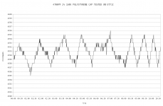
The first picture shows the readings of a single cap over the course of 10 minutes. Doesn't look all that great. I'll blame it on the meter.
Since this strategy isn't going to bring me any closer to my goal, I decided to take on another approach. Using another 4700pF polystyrene (of unknown exact value, that is) as a reference cap, I built a simple 50% divider together with the DUT and fed that with a 1kHz sine wave from my soundcard output at 0dBFS. Since the UT71C is a TrueRMS meter, it didn't have any troubles showing the soundcard max output value as 2.0899Vrms after a couple of seconds and then keep the reading steady. So I built a little fixture out of nested banana plugs to screw the DUT into (again to keep stray capacitance due to long leads to a minimum and maintain a good contact) and took some AC voltage readings. I then entered them into Calc, together with some math, and thus arrived at a new set of calculated capacitance values. To arrive at those values, I had to specify the capacitance of my reference capacitor. That value is only critical for absolute accuracy though, since the relative deviations from part to part are now exactly represented by the measured voltage levels.
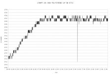
To get to the reference cap's capacitance, I put it on the meter once again, set to measure capacitance... Have a look at the second picture.
This time it took the meter about 7 minutes to settle! Not sure if this was due to some residual charge of the capacitor itself? Anyhow, from there on the value basically oscillated around a mean value with only 1pF up or down, which I'd call pretty good actually, compared to drifting around 5pF in either direction over the course of a minute!
Using the mean value of 4767pF for the reference cap, I calculated the capacitance for each DUT and put them in the below table, together with some 'arbitrarily picked' values I 'measured' beforehand with the meter set to capacitance.
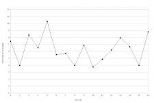
The 'measured' and calculated values differ by roughly 7pF, some more some less. See the third picture for a quick glance.
So, what did we (well, I, at least) learn today? Make yourself thoroughly familiar with your measurement equipment before you attempt to make some precise and repeatable measurements!

I could have easily lived with the absolute values being not totally accurate, since the meter is a rather cheap one after all (~150 is still a lot of money and I couldn't afford a more expensive one, but compared to a 500+ Fluke it's rather cheap). The results I got, however, were not far from being totally useless. I was about to pick the two best pairs out of 16 caps, 4700pF 2% polystyrene (which has a rather low temperature coefficient already). The caps are axial parts, so I simply bend the legs down, screwed them into two naked banana plugs and put those directly into the multimeter, to exclude the stray capacitance of the test leads. I gave the meter some time to settle, but noticed that it would not. Over the course of half a minute or so, the meter reading kept rising or falling about 10pF, which calculates out to roughly 2000ppm! Now, how am I supposed to find a close match if the meter readings are about as accurate as the printed tolerance on the part itself? Of course I could let the meter run for half an hour on each part, record the readings to the PC and then integrate them all to a final value, but that's too tedious for my taste. My 16 parts would have taken me a whole working day time, apart from having to keep the temperature reasonably constant....
The first picture shows the readings of a single cap over the course of 10 minutes. Doesn't look all that great. I'll blame it on the meter.
Since this strategy isn't going to bring me any closer to my goal, I decided to take on another approach. Using another 4700pF polystyrene (of unknown exact value, that is) as a reference cap, I built a simple 50% divider together with the DUT and fed that with a 1kHz sine wave from my soundcard output at 0dBFS. Since the UT71C is a TrueRMS meter, it didn't have any troubles showing the soundcard max output value as 2.0899Vrms after a couple of seconds and then keep the reading steady. So I built a little fixture out of nested banana plugs to screw the DUT into (again to keep stray capacitance due to long leads to a minimum and maintain a good contact) and took some AC voltage readings. I then entered them into Calc, together with some math, and thus arrived at a new set of calculated capacitance values. To arrive at those values, I had to specify the capacitance of my reference capacitor. That value is only critical for absolute accuracy though, since the relative deviations from part to part are now exactly represented by the measured voltage levels.
To get to the reference cap's capacitance, I put it on the meter once again, set to measure capacitance... Have a look at the second picture.
This time it took the meter about 7 minutes to settle! Not sure if this was due to some residual charge of the capacitor itself? Anyhow, from there on the value basically oscillated around a mean value with only 1pF up or down, which I'd call pretty good actually, compared to drifting around 5pF in either direction over the course of a minute!
Using the mean value of 4767pF for the reference cap, I calculated the capacitance for each DUT and put them in the below table, together with some 'arbitrarily picked' values I 'measured' beforehand with the meter set to capacitance.
Code:
DUT#	DUT-Voltage	Calculated	Measured
------------------------------------------------
1	1,0607		4625		4618
2	1,0594		4637		4633
3	1,0632		4603		4595
4	1,0590		4641		4634
5	1,0623		4611		4601
6	1,0590		4641		4635
7	1,0555		4672		4666
8	1,0477		4742		4738
9	1,0547		4679		4672
10	1,0546		4680		4676
11	1,0584		4646		4641
12	1,0550		4676		4670
13	1,0620		4614		4606
14	1,0609		4624		4617
15	1,0576		4653		4649
16	1,0644		4593		4584
The 'measured' and calculated values differ by roughly 7pF, some more some less. See the third picture for a quick glance.
So, what did we (well, I, at least) learn today? Make yourself thoroughly familiar with your measurement equipment before you attempt to make some precise and repeatable measurements!
Attachments
Nice work and write up. It is great your measured and calculated were very close.
I built a simple LCR meter. Here is a similar article: http://icom.hsr.ch/fileadmin/user_upload/icom.hsr.ch/publikationen/RLC_Meter_EN.pdf
Ultimately, I ended up purchasing an older impedance bridge. The General Radio 1650 or ESI 250 series are great instruments to have...even if you only use them once a year.
Sorry but you don't have test equipment with precision enough for the job, period.
You "see measured capacitors drift" but I bet the multimeter has some capacitor *inside* which also drifts by a minute amount, probably more or the same as the external one you are trying to measure, and you'll never know by how much, because it's part of the "reference" .
Compare it to measuring with a rubbered cloth tape measure such as used by tailors, "because that's what you have" , instead of measuring with a stainless steel ruler "which is what you need".
But anyway, maybe you do not need to measure the capacitors that exactly, you should measure the actual notch *frequency* which after all is your end goal.
easy to find impedance measurement setups just using the soundcard ADC and DAC
you do need a known reference impedance passive part - after that everything can be calibrated/ratioed out in better setups
hi Z input, low Z output active buffers are handy, as is range switching, gain , input protection...
a soundcard will do ratios and frequency to very high standards - beyond most passive component's accuracy
letting you measure a audio frequency notch filter transfer function directly
Last edited:
Sorry but you don't have test equipment with precision enough for the job, period.
That's true. But then again, I don't have the parts with precision enough, too. Metal film resistors with 50ppm tempco run away pretty fast, which might necessitate putting the whole thing in an oven. Or get a matched quad in one package with 5ppm and matched to 0.01%.
And precision measurement equipment is certainly something pretty nice to have, but I cannot justify spending thousands of bucks for the best of the best (sometimes I wish I could
)But anyway, maybe you do not need to measure the capacitors that exactly, you should measure the actual notch *frequency* which after all is your end goal.
And I certainly will, once it's done, But I prefer to start out as good as I can, so I don't have to fiddle with 6 settings afterwards. Besides trimpots and trimcaps having an even worse tempco than the other parts.
The variations seen may be a consequence of RF interference, which is almost everywhere these days.
Been thinking about that, too, but the rather low frequency seems somewhat strange to me.
You "see measured capacitors drift" but I bet the multimeter has some capacitor *inside* which also drifts by a minute amount, probably more or the same as the external one you are trying to measure, and you'll never know by how much, because it's part of the "reference" .
Any chance to 'hack' that cap for a better one? Silver mica, probably?
Could be modulation. Your first graph seems to show two different frequencies, with a switch between them at about 6:15. Or could it be temperature? Were these tests carried out in a thermostatically controlled environment (either heating or cooling)? Variations on the scale of a minute or so could come from a fan or heater switching on and off.Preamp said:Been thinking about that, too, but the rather low frequency seems somewhat strange to me.
UT DMM is 4000 count 40.00 nF is the lowest range setting specified to (1% plus +/-20 counts)
easy to see the modulation source ( it's the DMM)
reference cap is 04.70 nF on a perfect meter
you could get better accuracy on this meter measuring the frequency resonance shift in a LC fixture
frequency accuracy is much better> pick L near full scale
easy to see the modulation source ( it's the DMM)
reference cap is 04.70 nF on a perfect meter
you could get better accuracy on this meter measuring the frequency resonance shift in a LC fixture
frequency accuracy is much better> pick L near full scale
Last edited:
oops just realized this is 40K count machineBeen thinking about that, too, but the rather low frequency seems somewhat strange to me.
modulation is probably related to the DMM update rate showing up on lower scale readings.
04.700 nF display with possible errors of initial tolerance +/- 0.047 nF and display +/- 0.020 nF
still a frequency measurement reigns at full scale
Last edited:
Is this behaviour inherent to the CyrusTec chip or due to an external capacitor? In the datasheet I could only find a 470nF auto zero capacitor and a compensation cap (probably around 300pF) mentioned for the frequency measurement. Since they're smd, they're most probably ceramic. 470n is rather high a value for polystyrene or mica, but would that make a difference at all? Stacking some X7Rs might be doable... I don't know how exactly those chips work and the datasheet is not very comprehensive.
20 count error vs 5 count on a UT61E machine with CyrusTec chip
maybe the other error term is more stable after some data is accumulated and processed ? IDK
also it helps to keep your measuring in the top half of the scale me thinks
to check things closer try to target somewhere between 39nF to 20nF for the low range scale
if you meas. frequency you can tune the test fixture towards full scale
Last edited:
so you measured 10pF variation or well within the DMM's budget for the display error.
lessons learned
choosing cap values to cherry pick isn't a random number selection process.
or buy 5% caps and adjust to the measured freq with a select-in-test resistor hopefully your chosen notch frequency lands on the higher side of the DMM scale as well.
lessons learned
choosing cap values to cherry pick isn't a random number selection process.
or buy 5% caps and adjust to the measured freq with a select-in-test resistor hopefully your chosen notch frequency lands on the higher side of the DMM scale as well.
so you measured 10pF variation or well within the DMM's budget for the display error.
Sure, but I never knew that this error would oscillate with something like 15mHz! Is that actually within spec, too? The other functions have a similar error specified, but I actually get a constant reading after some settling time for things like resistance, VDC, VAC and IDC. I understand the error as an absolute error, like ie. a voltage being 1.0000V and the meter showing 0.9996V. If the meter would show me 0.9999 instead, 0.9996 ten seconds later, 1.0002 another 20 seconds later and then 1.0004 after another 10 sec, I'd immediately return/toss/curse it! Why is only the cap range behaving this strange? If it is actually due to some cheap external reference only, maybe there's something I can do about it without compromising the other functions?
Measuring values closer to the top end of the scale is certainly better, but I just happen to have 4n7 around and not 3n9 (and not a 60k count meter). And then again there's the tempco, which easily spoils the best matching if I don't pot all the parts afterwards. FWIW the meter's resolution is easily good enough, as I found a decently close match with parts 4 and 6. If you compare them to the rest of the range, tossing in any other two would have been a lot worse.
Attachments
I don't know the context of your application, but if it's about tuning a twin-T notch filter, there's a pretty simple in-situ trim procedure where only resistors must be adjusted, and no precision capacitors are needed: IEEE Xplore Abstract - Two-step precision tuning of twin-T notch filter.
Samuel
Samuel
Is there a copy available to non IEEE Members?
Sure, you can purchase it without membership.
I can outline the basic procedure if interested.
Samuel
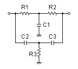
The fourth terminal is in series with R3, to temporarily remove this part.
I'm not sure how close the phase shift must be measured for a given attenuation; the easiest is probably with a 2-channel scope (looking both at the input and output).
He suggests a bridge setup; a bit too complicated to describe...
Samuel
I'm not sure how close the phase shift must be measured for a given attenuation; the easiest is probably with a 2-channel scope (looking both at the input and output).
He suggests a bridge setup; a bit too complicated to describe...
Samuel
- Status
- This old topic is closed. If you want to reopen this topic, contact a moderator using the "Report Post" button.
- Home
- Design & Build
- Equipment & Tools
- Matching capacitors with a multimeter