I don't know the context of your application, but if it's about tuning a twin-T notch filter, there's a pretty simple in-situ trim procedure where only resistors must be adjusted (...)
Thanks Samuel, that's certainly something to consider. Since I'm only out for a single frequency close to 1kHz, the question arises whether it's better to achieve a constantly deep notch with matched low-tempco parts, or use potentiometers with a rather higher tempco and have to re-adjust the filter every x minutes. Since I don't have any 'physical' experience with such a filter yet, I cannot say how much it will drift away over the course of, say, half an hour. I definitely prefer the set-and-forget approach here, when a reasonable depth and stability can be achieved that way. "Reasonable" is a thing I have to define a little closer for sure, but that's something I'll have to find out first
") .
.On the other hand I'd surely like to get rid off that cap meter oscillation phenomenon, too. The hacker in me would have taken the meter apart already, but since it's my only 40000 count one, I don't want to brick it... Decisions, decisions
I've found something more in the datasheet of the Cyrustek chip.
First, there's another 100nF ceramic called "CREF" or "reference capacitor", but it is not mentioned what it's supposed to be there for.
And then there're CINT and BUF, namely the integration capacitor and -resistor, fitted with 33nF (through-hole!) and 200kOhm. The datasheet quotes the following for the example circuit: "In capacitance mode, change 33nF to 220nF or change 200KΩ to 1MΩ". Looking at the schematic of the VC940, which is pretty close to the 71C, this change is omitted completely. Since the datasheet is far from extensive, it doesn't tell why the integration cap should be increased for capacitance measurements, but to me this sounds like a possible explanation. Putting a cap in parallel and running another cap measurement seems easy enough to try ...
First, there's another 100nF ceramic called "CREF" or "reference capacitor", but it is not mentioned what it's supposed to be there for.
And then there're CINT and BUF, namely the integration capacitor and -resistor, fitted with 33nF (through-hole!) and 200kOhm. The datasheet quotes the following for the example circuit: "In capacitance mode, change 33nF to 220nF or change 200KΩ to 1MΩ". Looking at the schematic of the VC940, which is pretty close to the 71C, this change is omitted completely. Since the datasheet is far from extensive, it doesn't tell why the integration cap should be increased for capacitance measurements, but to me this sounds like a possible explanation. Putting a cap in parallel and running another cap measurement seems easy enough to try
...Measuring values closer to the top end of the scale is certainly better, but I just happen to have 4n7 around and not 3n9 (and not a 60k count meter). And then again there's the tempco, which easily spoils the best matching if I don't pot all the parts afterwards. FWIW the meter's resolution is easily good enough, as I found a decently close match with parts 4 and 6. If you compare them to the rest of the range, tossing in any other two would have been a lot worse.
its a crappy meter masquerading as higher count machine. double digit count uncertainty is the crap index > on top of that playing in the lower part of the range certainly doesn't help you get significant digits for a reasonable measurement. Best hack > cover the last digit with black electrical tape.
and use basic lab measurement practices when reporting / collecting data.
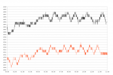
Looks like it is not the integration capacitor. I put a 220nF MKS in parallel to the 33nF and tested the exact same 4700pF from the first post, first picture.
The black graph shows the result of the mod. The oscillation amplitude is not gone, but only half as severe as yesterday. Unfortunately this is not due to the integration cap, as the red graph shows. I removed the additional 220nF immediately after the acquisition and re-ran the measurement without it. The overall capacitance is a little lower (by about 13pF), but the oscillation remains basically the same. One point for the EMI theory I guess...
The black graph shows the result of the mod. The oscillation amplitude is not gone, but only half as severe as yesterday. Unfortunately this is not due to the integration cap, as the red graph shows. I removed the additional 220nF immediately after the acquisition and re-ran the measurement without it. The overall capacitance is a little lower (by about 13pF), but the oscillation remains basically the same. One point for the EMI theory I guess...
Attachments
it is what it is > RS-232 is reporting front panel readings at specific time intervals not synched to the update rate /readings that are corrupted from operating at low end of the lowest scale.
haha lets take a deeper dive into jitter and noise
measure <1 nF cap would help the magnitude /
IMO he'd be better off massaging the data in a spreadsheet and truncating some digits according to the instruments specs at that range E.g. its got more resolution than the front end can handle.
haha lets take a deeper dive into jitter and noise
measure <1 nF cap would help the magnitude /
IMO he'd be better off massaging the data in a spreadsheet and truncating some digits according to the instruments specs at that range E.g. its got more resolution than the front end can handle.
Last edited:
It might be easier to see what is going on if you low-pass filter the data to remove the spikes but preserve the underlying variation.
Sure, but like I said, I'm not going to record 20+ minutes for a single capacitor and then low-pass that data.
haha lets take a deeper dive into jitter and noise
measure <1 nF cap would help the magnitude /
Here's a <1nF ceramic for you. Care to guess the value it was labeled with?
Attachments
I venture to say something is wrong with your DMM and / or your procedure inquire with the other test gear forum to compare. I ran some testing with my UT61E and I get satisfactory results 1st setting range manually, relative zero, and then measures rock stable within a second or 2 , repeatable and slight drift over 1-2 pF. at ~15nF on 22nF range then rechecked with new value 150 pF still good.
IMO 7 minutes is downright ridiculous!
IMO 7 minutes is downright ridiculous!
Last edited:
IMO 7 minutes is downright ridiculous!
Second that. I've sent an inquiry to the supplier.
- Status
- This old topic is closed. If you want to reopen this topic, contact a moderator using the "Report Post" button.
- Home
- Design & Build
- Equipment & Tools
- Matching capacitors with a multimeter