That could be. So this is probably due to the phase of the input signal relative to the sampling of the ADC.
Looking carefully at the second plot from Demian in post #2205 there does seem to be a small difference between the two cycles also in this case.
On closer inspection I see that as well. I'm not sure if there is anything relating to the phase of the leading edge and the nature of the sampling with the delta-sigma process in the ADC. I'll brek out the digital generator to see if I can find anything but not right now. Low pass filtering eliminates it. I may bug my friends at AKM for some explanation.
"free" as in free beer, or as in free speech? That makes a huge difference...
The issue with ASIO is the license. Its not a GNU-GPL license so you can't add it to most open source projects with out violating some license somewhere. Audacity gets around this by having users compile it in themselves which is compliant but much more involved. The compiled version cannot be shared.
I am mostly using SoundEasy, it is the capability to look at CSD and Wavelets that I generally do not find in other software because I sometimes look at time scale within 0.3ms. The lower level CSD over a wider time range is what I am starting to look into. On my Windows 7 machines, I seem to be getting a higher noise floor in CSD readings than my XP machine. I have compared a few different USB sound cards, and they all give cleaner results on my XP machine.
Unfortunately, SoundEasy WASAPI does not work with USB sound cards for some reason.
So currently I am kind of stuck.
What about asio4all, do you have tried?
On closer inspection I see that as well. I'm not sure if there is anything relating to the phase of the leading edge and the nature of the sampling with the delta-sigma process in the ADC. I'll brek out the digital generator to see if I can find anything but not right now. Low pass filtering eliminates it. I may bug my friends at AKM for some explanation.
My idee for an possible explanation in more detail is:
The ADC is 128-oversampling (at 40k-ish fs). If the clock of the generator and the ADC are not 100% synchronous and the edge is rising very fast a different amount of "high samples" will be in the 128 samples for each rising edge. Thus filtering and decimation to the sample rate we are actually seeing will produce different values around the edge.
What about asio4all, do you have tried?
ASIO4All is for adding ASIO capability to drivers. But the app that I use does not support ASIO.
There is another app that may be an odd but usable work around that I have used to connect ASIO drivers with applications that don't support ASIO: VB-Audio Virtual Apps Its more than a little confusing to setup and use but once you have it figured out it works quite well with no bit twiddling.
The issue with ASIO is the license. Its not a GNU-GPL license so you can't add it to most open source projects with out violating some license somewhere. Audacity gets around this by having users compile it in themselves which is compliant but much more involved. The compiled version cannot be shared.
If this ASIO is being talked about (I don't use it, just g**gled for it):
< asio C++ library >
then the license seems harmless:
Boost Software License - Version 1.0 - August 17th, 2003
Permission is hereby granted, free of charge, to any person or organization
obtaining a copy of the software and accompanying documentation covered by
this license (the "Software") to use, reproduce, display, distribute,
execute, and transmit the Software, and to prepare derivative works of the
Software, and to permit third-parties to whom the Software is furnished to
do so, all subject to the following:
The copyright notices in the Software and this entire statement, including
the above license grant, this restriction and the following disclaimer,
must be included in all copies of the Software, in whole or in part, and
all derivative works of the Software, unless such copies or derivative
works are solely in the form of machine-executable object code generated by
a source language processor.
THE SOFTWARE IS PROVIDED "AS IS", WITHOUT WARRANTY OF ANY KIND, EXPRESS OR
IMPLIED, INCLUDING BUT NOT LIMITED TO THE WARRANTIES OF MERCHANTABILITY,
FITNESS FOR A PARTICULAR PURPOSE, TITLE AND NON-INFRINGEMENT. IN NO EVENT
SHALL THE COPYRIGHT HOLDERS OR ANYONE DISTRIBUTING THE SOFTWARE BE LIABLE
FOR ANY DAMAGES OR OTHER LIABILITY, WHETHER IN CONTRACT, TORT OR OTHERWISE,
ARISING FROM, OUT OF OR IN CONNECTION WITH THE SOFTWARE OR THE USE OR OTHER
DEALINGS IN THE SOFTWARE.
That is in strong contrast to GPL V2 that taints everything that comes in contact
with it.
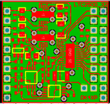
BTW I got this week the first LTC2500-32 ADC and made a layout for it.
It is just 1" * 1" and has 2 LT3042 regulators for the pos. voltages, a low drop
for the neg. voltage for the buffer, the buffer, the ADC and a LT6655 reference.
I will use the SPI interface to connect it to a BeagleBoneBlack.
The sample rate generator will be another stamp-sized board.
This is still highly experimental, far from a cooking recipe.
cheers, Gerhard
Attachments
I tried their HiFicable & ASIO bridge using babyface pro running Win7 on. MacBook Pro boot camp, running through this setup is noisier than running directly through the MME driver directly.
Comparison of the two:

This is what the Babyface Pro looks like on the XP machine

This is the Echo Indigo iOS on the XP machine

This is an example of what happens on the Win7 with output at 48KHz and input at 96KHz set in Windows sound devices:

I tried their HiFicable & ASIO bridge using babyface pro running Win7 on. MacBook Pro boot camp, running through this setup is noisier than running directly through the MME driver directly.
Possibly the sound engine has some compromises in that implementation. Typically truncation without dither or sample rate conversion. I'll fire up the hifi cable and try a test or two. In my system with 5 asio drivers it gets really confusing fast.

The modulation in the overshot (post 5411691) might be an argument for why an digital output for the RTX6001 would be useful.
This would allow that the clocks of the analyzer and the DUT (can) run synchronous (if the DUT allows that) and so eliminate a potential source of mess in the data.
This would allow that the clocks of the analyzer and the DUT (can) run synchronous (if the DUT allows that) and so eliminate a potential source of mess in the data.
It's been fairly quit here for a while. I hope that it is because the RTX6001 is now used to test your latest and greatest audio designs instead of testing the analyzer itself 
After 300k views on this thread perhaps it is time for some additional info about the RTX6001.
Some users have asked for the possibility of adding a digital output. I now have the possibility to reveal some new information regarding this.
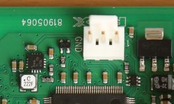
I am a bit surprised that, at least as far as I know, no one has been curious enough to investigate what the small 3-pin connector on the USB interface was intended for
It is actually a (CMOS level) SPDIF signal! It is a digital version of the audio sent to the DAC. With a couple of resistors and a capacitor it is possible to get a SPDIF output. The 3-pin connector is electrically connected to the PC so I suggest to use a transformer as well, to isolate it. And I also suggest to keep the output isolated from the chassis of the RTX6001 to avoid ground loops.
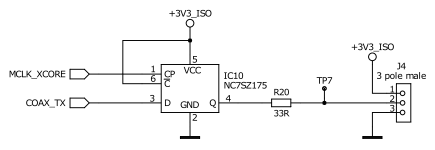
A 220 ohm resistor in series with the output from the USB Board and a 110 ohm resistor in parallel with the SPDIF output connector will get you close to the recommended levels and impedances for SPDIF. Or perhaps 210 and 107 ohm if you want to fine-tune the impedance, assuming that the transformer will also contribute a little to the output impedance.
SPDIF is simple to make. But it is also possible to implement an AES output or a Toslink output. A 3.3 V supply is available on the connector, so no additional supply is needed. A schematic of the output circuit and the connector is attached. As you can see, the output is clocked by the master clock of the analyzer. The clock goes through the isolator, which does add some jitter. Since the clock comes from the crystal oscillators on the Main Board of the analyzer, the unit has to be switched on to activate the output. Otherwise non-standard frequencies would be sent out, which can be confusing.
GND and pin 1 are marked on the PCB, so with the schematic it should be fairly easy to get the connections right.
A simple way to implement it is to use a thin coax cable (for SPDIF) and take it through one of the slots in the rear plate.
The modifications are DIY only. RTX does not deliver any boards or provide any other support in relation to this. Be careful when working on the interior of the RTX6001. First of all, you must of course disconnect the supply. And avoid damaging the unit. Otherwise the warranty may be void.
After 300k views on this thread perhaps it is time for some additional info about the RTX6001.
Some users have asked for the possibility of adding a digital output. I now have the possibility to reveal some new information regarding this.
I am a bit surprised that, at least as far as I know, no one has been curious enough to investigate what the small 3-pin connector on the USB interface was intended for
It is actually a (CMOS level) SPDIF signal! It is a digital version of the audio sent to the DAC. With a couple of resistors and a capacitor it is possible to get a SPDIF output. The 3-pin connector is electrically connected to the PC so I suggest to use a transformer as well, to isolate it. And I also suggest to keep the output isolated from the chassis of the RTX6001 to avoid ground loops.
A 220 ohm resistor in series with the output from the USB Board and a 110 ohm resistor in parallel with the SPDIF output connector will get you close to the recommended levels and impedances for SPDIF. Or perhaps 210 and 107 ohm if you want to fine-tune the impedance, assuming that the transformer will also contribute a little to the output impedance.
SPDIF is simple to make. But it is also possible to implement an AES output or a Toslink output. A 3.3 V supply is available on the connector, so no additional supply is needed. A schematic of the output circuit and the connector is attached. As you can see, the output is clocked by the master clock of the analyzer. The clock goes through the isolator, which does add some jitter. Since the clock comes from the crystal oscillators on the Main Board of the analyzer, the unit has to be switched on to activate the output. Otherwise non-standard frequencies would be sent out, which can be confusing.
GND and pin 1 are marked on the PCB, so with the schematic it should be fairly easy to get the connections right.
A simple way to implement it is to use a thin coax cable (for SPDIF) and take it through one of the slots in the rear plate.
The modifications are DIY only. RTX does not deliver any boards or provide any other support in relation to this. Be careful when working on the interior of the RTX6001. First of all, you must of course disconnect the supply. And avoid damaging the unit. Otherwise the warranty may be void.
Attachments
That's great!I have a plane,design a PCB with SPDIF、AES、OPTICAL and maybe the I2S via HDMI,I'd like to use WM8805 with local oscillator as a master mode,it's jitter is 50ps RMS with inside DPLL.I'd like use a MCU to control the WM8805 and configuration the DPLL for the best peformance.Or maybe I should use the I2S----->WM8805----->DIGITAL OUTPUT?
Hi Jens,
I think most of us are pleased enough with your analyser to treat it as the test equipment that it is. I would be very cautious about interfering with the proper operation of the unit. I assumed it was a test point for factory use.
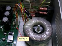
However, with this information, even I can implement an SPDIF output. The required transformer will come from a dead CD player. Does the internal supply have enough capacity to run a simple driver for optical? May as well add that too. The digital output will be a help for me.
Thank you Jens!
-Chris
I think most of us are pleased enough with your analyser to treat it as the test equipment that it is. I would be very cautious about interfering with the proper operation of the unit. I assumed it was a test point for factory use.
However, with this information, even I can implement an SPDIF output. The required transformer will come from a dead CD player. Does the internal supply have enough capacity to run a simple driver for optical? May as well add that too. The digital output will be a help for me.
Thank you Jens!
-Chris
- Home
- Design & Build
- Equipment & Tools
- DIY Audio Analyzer with AK5397/AK5394A and AK4490