Does that noise change if you play some test signal through the USB/DAC?
Also, how is the USB interfaced to the DAC? For example, some USB-to-I2S converters output an I2S signal as soon as they are connected to USB. If the DAC chip has some internal processing of the I2S data stream, you may see the residual noise of this processing. For example, the DDDAC does this, I believe.
That is a good pointer. The noise does seem to go away when i play a test tone.
Interface to the DAC is I2S (i use exau2i).
Thanks. Will post some more pictures. Hopefully not too out of topic. Using the RTX6001 i'm able to get a much better insight into the performance of the DAC compared to sound cards i was using earlier.
I finally found a Windows (7) desktop PC for upgrading the firmware. First I had no success (with any of the USB2 ports). Then in a whim I connected an unpowered USB Hub connected the RTX 6001 to that and now it worked.
P.S.
-140dB is 10^-7 (for voltage like units) so 0.1 ppm or 100 ppb.
P.S.
Ups, I went to far in diminishing billions for the use in English.Yes -140dB is 0.1 ppb ...
-140dB is 10^-7 (for voltage like units) so 0.1 ppm or 100 ppb.
The mains hum in unbalanced cabling is quite sensitive to the quality of the connection.
To visualize this I have made several measurements of an Soekris DAM DAC, playing a 1kHz -100dBV signal, from its raw output (unbalanced and unbuffered connected to the DAM's switched resistor ladder). The DAM is floating AC powered. The RTX6001 input is set to 0dBV.
The comments on "quality" refer to the mains hum.
First the recommended pseudo balanced connection (cabling no 17 of ...). The quality depends on the point to which you connect the separate ground line from the dedicated RTX terminal. The first is the best way I found, the second a worse point.
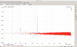
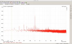
All the following pictures are connections where the pin 1 and 3 of the input are shorted at the RTX side. One thing they have in common is the much better overall noise floor.
In this row all pictures are taken by using a commercial Netric XLR-BNC adapter, a BNC cable and a commercial no-name BNC-RCA adapter. The connector on the RCA side connected "easily", also the BNC cable connectors were perhaps not the best. As a result the quality depended much on where you pushed to the cable (from best to worst result )
)
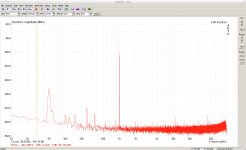
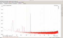
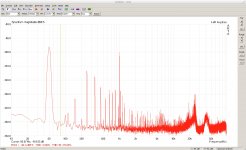
With the commercial Netric XLR-BNC adapter, a no-name BNC-RCA(female) adapter and a good RCA cable whose connectors had firm contact, I slightly improved the best above result. And here pushing the cable had no more influence.
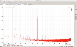
With a custom made XLR to RCA cable with good connectors, a reliable, and slightly better result was obtained.
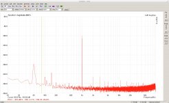
With the same cable as above, by cleaning all connectors with contact spray the 50Hz peak can be reduced by further 5dB. The peak is now below the noise floor of the pseudo balanced cabling.
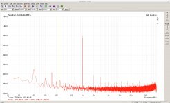
To visualize this I have made several measurements of an Soekris DAM DAC, playing a 1kHz -100dBV signal, from its raw output (unbalanced and unbuffered connected to the DAM's switched resistor ladder). The DAM is floating AC powered. The RTX6001 input is set to 0dBV.
The comments on "quality" refer to the mains hum.
First the recommended pseudo balanced connection (cabling no 17 of ...). The quality depends on the point to which you connect the separate ground line from the dedicated RTX terminal. The first is the best way I found, the second a worse point.


All the following pictures are connections where the pin 1 and 3 of the input are shorted at the RTX side. One thing they have in common is the much better overall noise floor.
In this row all pictures are taken by using a commercial Netric XLR-BNC adapter, a BNC cable and a commercial no-name BNC-RCA adapter. The connector on the RCA side connected "easily", also the BNC cable connectors were perhaps not the best. As a result the quality depended much on where you pushed to the cable (from best to worst result


With the commercial Netric XLR-BNC adapter, a no-name BNC-RCA(female) adapter and a good RCA cable whose connectors had firm contact, I slightly improved the best above result. And here pushing the cable had no more influence.

With a custom made XLR to RCA cable with good connectors, a reliable, and slightly better result was obtained.

With the same cable as above, by cleaning all connectors with contact spray the 50Hz peak can be reduced by further 5dB. The peak is now below the noise floor of the pseudo balanced cabling.

A discovery of some monkey testing is that the overflow indicator is not always working reliable. RTX out set to 0dBV. The signal played is the ARTA jitter test signal.
First with input set to 0dBV - a clean signal with -10dBFS peak.
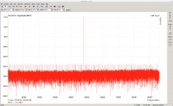
When I set the input to -10dBV the overflow indicator on the RTX lights and the measurement looks ugly - as expected.
With input set to -20dBV the overflow indicator is OFF and most of the time (long enough to make a good average) the measurement looks like that.
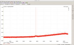
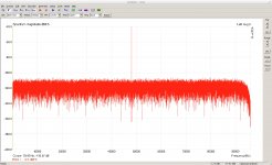
From time to time it jumps to that, but still no overflow indicated.
First with input set to 0dBV - a clean signal with -10dBFS peak.

When I set the input to -10dBV the overflow indicator on the RTX lights and the measurement looks ugly - as expected.
With input set to -20dBV the overflow indicator is OFF and most of the time (long enough to make a good average) the measurement looks like that.

From time to time it jumps to that, but still no overflow indicated.

Some more monkey testing. The low level high frequency artefacts of some signals of the DAC section.
Output was set to 0dBV, input to -20dBV, the signal level is always -40dB.
First some sine signals (100Hz, 500Hz, 1kHz, 10kHz, 12kHz)
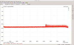
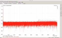
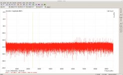
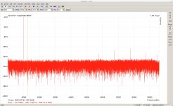
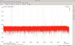
Two simultaneous sines of 10kHz and 11kHz
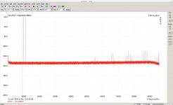
A 1kHz triangle.
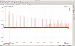
Well, the only conclusion up to now - better to reduce the signal strength by analog attenuation than digital, if the low level HF part really is of importance.
Output was set to 0dBV, input to -20dBV, the signal level is always -40dB.
First some sine signals (100Hz, 500Hz, 1kHz, 10kHz, 12kHz)


Two simultaneous sines of 10kHz and 11kHz

A 1kHz triangle.

Well, the only conclusion up to now - better to reduce the signal strength by analog attenuation than digital, if the low level HF part really is of importance.
Last edited:
First the recommended pseudo balanced connection (cabling no 17 of ...)...
...the following pictures are connections where the pin 1 and 3 of the input are shorted at the RTX side. One thing they have in common is the much better overall noise floor.
I would've expected it the other way round. Why is the noise floor lower with the single ended connection?
by cleaning all connectors with contact spray the 50Hz peak can be reduced by further 5dB. The peak is now below the noise floor of the pseudo balanced cabling.
Is it really the contact spray that does the trick? Or is it just the repeated make-and-break of the connection that cleans the connectors?
I would've expected it the other way round. Why is the noise floor lower with the single ended connection?
This stuff is all over the page because noting is calibrated.
The reason the single end has "lower noise" is because it is half the voltage of balanced, (-6dB) less voltage.
Recommendation: start from something solid and build from something solid, something repeatable and build from there.
DT
Well, the source is single ended, so there is no "true" balanced connection. The different setups differ in at which point (at the source or analyzer side) and how "ground" is connected to the negative differential input.I would've expected it the other way round. Why is the noise floor lower with the single ended connection?
As the RTX6001 dedicated ground terminal is "only" screwed to the front plate and probably the source's best ground terminal is its RCA connector, maybe the direct unbalanced connection is here just the better grounds connection.
But I am also a bit surprised that even the not so good "unbalanced" connections show consistently an other quality of the ground floor.
Is it really the contact spray that does the trick? Or is it just the repeated make-and-break of the connection that cleans the connectors?
No repeated make-and-break had only a slight effect, but gave me the hint that I should thoroughly clean the connectors. Especially the RCA-outputs of the DAC had already been in use for several years.
This stuff is all over the page because noting is calibrated.
How do you know? The signal source was "an Soekris DAM DAC, playing a 1kHz -100dBV signal", and the 1 kHz peak always shows up at the same amplitude in the plots. That made me think that the 6 dB difference between balanced and single ended was compensated by the calibration in the software according to the different ways the RTX input was used in these tests.
I have only now realised that the levels shown in the plots are in dBFS, not in dBV. So the data were not calibrated in absolute terms, which isn't great.
Everyone: CALIBRATE YOUR DATA IN A MEANINGFUL WAY!!! PLEASE!!!
The reason the single end has "lower noise" is because it is half the voltage of balanced, (-6dB) less voltage.
That explanation would work if the calibration would not account for the 6 dB difference between the balanced / single ended tests. But again, the test signal shows up a the same level in all tests, so I thought the software compensated for this difference somehow.
zfe:
- How did you calibrate the data in these tests?
- Can you provide absolute levels (in Volts or dBV, for example)?
Ups, I forgot to mention the input setting was 0dBV, so dBV and dBFS coincide.How do you know? The signal source was "an Soekris DAM DAC, playing a 1kHz -100dBV signal", and the 1 kHz peak always shows up at the same amplitude in the plots. That made me think that the 6 dB difference between balanced and single ended was compensated by the calibration in the software according to the different ways the RTX input was used in these tests.
I have only now realised that the levels shown in the plots are in dBFS, not in dBV. So the data were not calibrated in absolute terms, which isn't great.
Everyone: CALIBRATE YOUR DATA IN A MEANINGFUL WAY!!! PLEASE!!!
That explanation would work if the calibration would not account for the 6 dB difference between the balanced / single ended tests. But again, the test signal shows up a the same level in all tests, so I thought the software compensated for this difference somehow.
zfe:
- How did you calibrate the data in these tests?
- Can you provide absolute levels (in Volts or dBV, for example)?
I did not change anything, including signal levels, at the source side for all the tests in this post!
There is no need to compensate something if you use unbalanced or "balanced" (that is connecting a unbalanced source input with "no 17" cabling), you get the same absolute values, as e.g. my above measurements show. And it produces the correct absolute values also unbalanced. That is with 0dbV setting you read 1VRMS for a sine signal on your voltmeter when the RTX displays 0dBFS!
You get the 6dB drop only for unbalanced output of the RTX, not with the input with and XLR-BNC adapter or alike.
While measuring noise with ARTA, the good practice will be to display them in dBV/rtHz (choose PSD under Spectrum Scaling), and have ARTA correctly calibrated.
Then people don't need to know your inputting setting and FFT length to figure out the actual noise level.
That might be a good idea if you investigate some DUT, but not necessarily if you try to test the limits of the analyzer itself. You than can not ignore the settings. And I find it more useful to see in which region of the ADC (so FS label) I am. Something like a double scale would satisfy probably everyone
That explanation would work if the calibration would not account for the 6 dB difference between the balanced / single ended tests. But again, the test signal shows up a the same level in all tests, so I thought the software compensated for this difference somehow.
I explained the 6 dB difference here
Jens
But that was related to the noise at the RTX output.
The data in post 1944 show different noise levels for different ways of connecting the DUT to the RTX input. I would have expected the Rane No 17 connection to give lower noise than a single ended connection using a SE-to-XLR adapter at the RTX input. The Rane No 17 connection avoids the ground loop via the RTX chassis (assuming the signal source is grounded) and common mode noise between the RTX input pins 2 and 3 will be cancelled.
However, the data in post 1944 seem to show the opposite. I am just curios to understand these effects so I can use this to make the best possible measurements.
... I would have expected the Rane No 17 connection to give lower noise than a single ended connection using a SE-to-XLR adapter at the RTX input. The Rane No 17 connection avoids the ground loop via the RTX chassis (assuming the signal source is grounded) and common mode noise between the RTX input pins 2 and 3 will be cancelled.
The DUT is floating (as I wrote) it is powered with something alike a 2-prong AC adapter.
A further peculiarity is that it is a 620 Ohm resistive load (alike a termination with that valued resistor). That explains why it has a very low noise floor. It only has tons of harmonics due to the nature of its signal generation as R2R-DAC.
I observed that the noise floor of the DAM, no signal playing, with the Rane No 17 connection (red curve) looks very alike the noise floor of the RTX when leaving the input of the RTX unconnected (green curve).
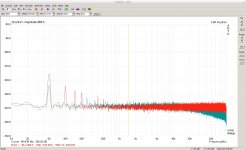
This might be coincidence, but... ?!?
When I plug in the input of the RTX a XLR plug with a 620R resistor in-between pin 2 and 3 (red curve - green as above) the noise floor drops considerably. And this is the picture I essentially would also expect to see from the DAM, with no signal playing, as I measure 625R in-between pin 2 and 3 with the Rane No 17 connection connected to the DAM - as expected by the specs.
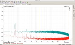
P.S. 0dBFS=0dBV (thus input switch to 0dBV)

This might be coincidence, but... ?!?
When I plug in the input of the RTX a XLR plug with a 620R resistor in-between pin 2 and 3 (red curve - green as above) the noise floor drops considerably. And this is the picture I essentially would also expect to see from the DAM, with no signal playing, as I measure 625R in-between pin 2 and 3 with the Rane No 17 connection connected to the DAM - as expected by the specs.

P.S. 0dBFS=0dBV (thus input switch to 0dBV)
The noise of an active circuit is not determined by it's output resistance/impedance.
A power amplifier with 1R output impedance can be way more noisy than a pre-amp with 100R output impedance.
The DAM is a R2R DAC. With no signal playing it is a pure resistive network with the mentioned resistance between the output pins. I can measure this resistance with a meter inbetween the pins.
There might be some cupeled in noise from the other components. Moreover there is 1.2nF capacitor parallel to the pins (of the analog output lowpass filter of the DAC). This one I might need still to add to my "simulator".
It's not about if there is signal playing, the Soekris DAM have ICs and transistors on it, so as long as power is on it's an active circuit.
Not sure if power is on during your test, but your own measurement have indicated that something is not right/complete in your "simulation".
Not sure if power is on during your test, but your own measurement have indicated that something is not right/complete in your "simulation".
- Home
- Design & Build
- Equipment & Tools
- DIY Audio Analyzer with AK5397/AK5394A and AK4490